Summary of Burning atmega328-pu and atmega328p-pu bootloader
This article explains how to burn the bootloader onto ATmega328 (ATMEGA328-PU / ATMEGA328P-PU) using an Arduino as ISP. It covers required hardware components, breadboard wiring connections (Arduino pins to ATmega pins, power, ground, crystal, caps, and pull-up resistor), and mentions the software step without detailed commands. Follow the listed connections and components to successfully bootload the microcontroller.
Parts used in the ATmega328 Bootloader Project:
- Arduino board (any type)
- ATMEGA328-PU or ATMEGA328P-PU
- 16 MHz oscillator
- 18-22 pF capacitors (x2)
- 10 kΩ resistor
- Breadboard
- Jumper wires
Burning the boot loader in an atmega328 could be somewhat tricky but if u follow these steps correctly youll be able to bootload any type of atmega328 micro controller ..
Step 1: “setting up the hardware”
– An Arduino board (any type)
– 18-22pf capacitors (x2)
– 16 MHZ oscilator
– Breadboard
– 10 Kohm resistor
– Jumper wires
– ATMEGA328-PU or ATMEGA328P-PU
– Bread board
 .
.
.
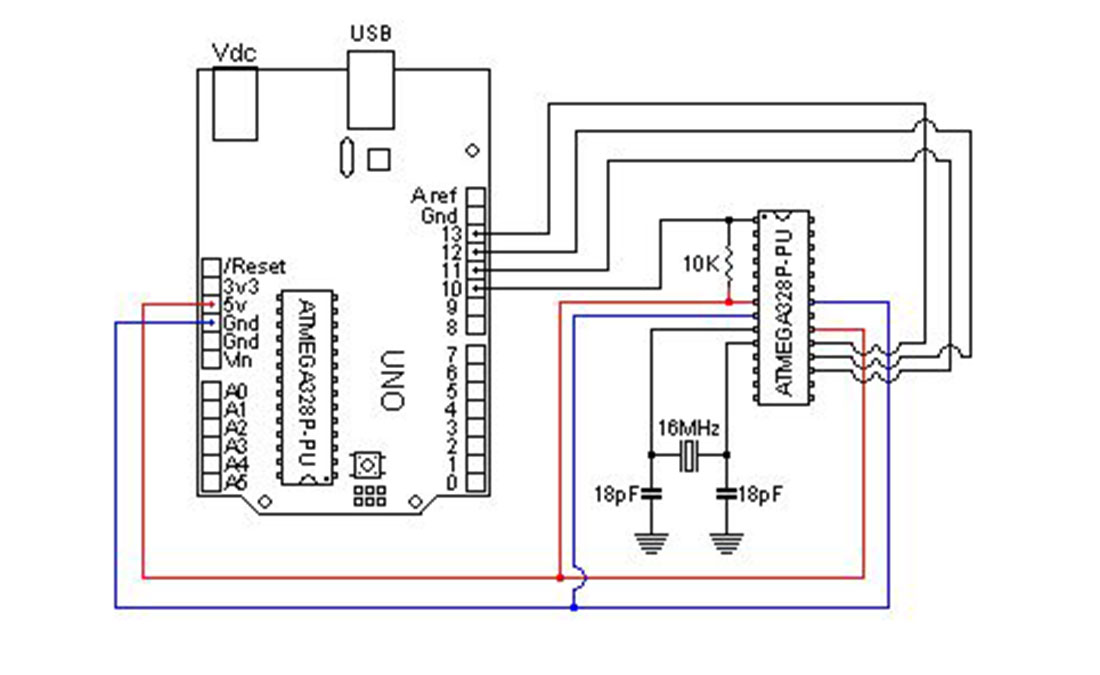
Assemble everything as shown in the figure (on a bread board) :
– arduino board (pin10)->breadboard (pin1)
– arduino board (pin11)->breadboard (pin17)
– arduino board (pin12)->breadboard (pin18)
– arduino board (pin13)->breadboard (pin19)
– (pin 7 ) and (pin20) of breadboard ->+5v of arduino board
– (pin8) and (|pin 22) of breadboard ->gnd of arduino board
– 10 Kohm resistor from(pin 1 ) to +5V
-16 MHZ oscilator from (pin 9 ) to (pin 10)
– 18-22pf caps : first one from (pin 9) to gnd ,second one from pin 10 to gnd
.
.
.
.
..
Now for the hard part made easy .
.
.The software.
For more detail: Burning atmega328-pu and atmega328p-pu bootloader
- What hardware is required to burn the bootloader onto an ATmega328?
An Arduino board, ATMEGA328-PU or ATMEGA328P-PU, 16 MHz oscillator, two 18-22 pF capacitors, a 10 kΩ resistor, a breadboard, and jumper wires. - How do I connect Arduino pins to the ATmega328 on the breadboard?
Connect Arduino pin 10 to ATmega pin 1, pin 11 to pin 17, pin 12 to pin 18, and pin 13 to pin 19 as described in the article. - Where should I connect power and ground for the ATmega328?
Connect breadboard pins 7 and 20 to Arduino +5V, and breadboard pins 8 and 22 to Arduino GND. - How is the reset pull-up resistor wired on the ATmega328?
Place a 10 kΩ resistor from ATmega pin 1 to +5V. - How do I connect the 16 MHz oscillator and capacitors?
Install the 16 MHz oscillator between ATmega pins 9 and 10, and connect one 18-22 pF capacitor from pin 9 to GND and the other from pin 10 to GND. - Are specific capacitor values required for the crystal?
Yes, use two capacitors of 18-22 pF each as specified. - Can any Arduino board be used as the programmer?
The article states any type of Arduino board can be used. - Does the article provide software instructions for burning the bootloader?
The article mentions the software step but does not provide detailed software commands.