Summary of CC2420 Radio
This article details the setup and programming of the CC2420DBK development kit, featuring the CC2420 ZigBee radio chip and Atmega128L microcontroller. It guides users through installing WinAVR and AVR Studio, testing wireless links between two boards, and creating custom C projects in AVR Studio to compile and flash HEX files for the hardware.
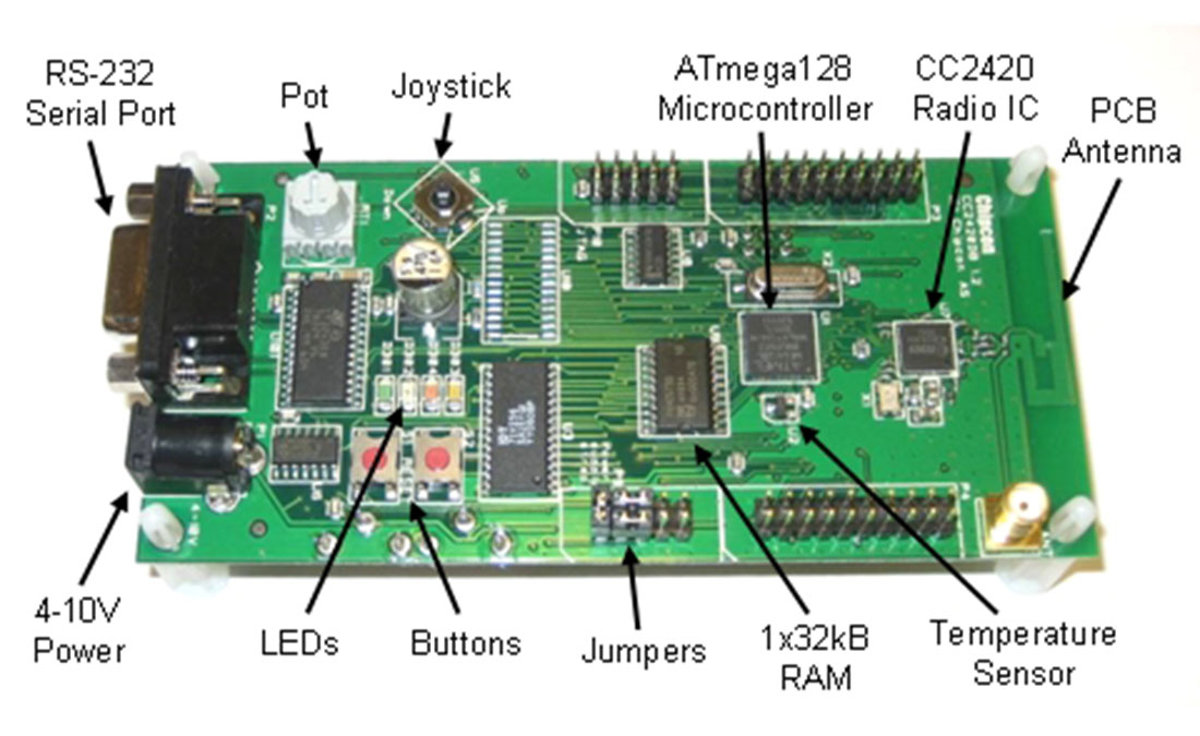
Parts used in the CC2420 Radio Project:
- Chipcon CC2420 radio
- Atmel Atmega128L microcontroller
- 32kB external RAM
- RS-232 connector
- Buttons (RESET S1, S2)
- Mini joystick (U5)
- Four LED's
- Temperature sensor
- Potentiometer
- On-board antenna
- 9V battery connector
- General purpose connectors
- Jumper pins
Introduction
The Chipcon (now owned by Texas Instruments) CC2420 is a commercial radio chip that complies with the ZigBee wireless standard. We have CC2420DBK development kits available for your project. Each development kit comes with 2 development boards (2 radios). Each development board has a Chipcon CC2420 radio, an Atmel Atmega128L microcontroller, 32kB of external RAM, an RS-232 connector, buttons, a mini joystick, four LED’s, a temperature sensor, a potentiometer, an on-board antenna, a 9V battery connector, and assorted general purpose connectors. Free software is available for programming the CC2420 radio, and compiling C code for the Atmel microcontroller. Chipcon has developed C libraries for communicating with the CC2420 radio from the Atmel microcontroller.
The microcontroller has two built-in options that can be used for communicating with the 6.111 Labkit: an RS-232 serial port, and a high-speed SPI port. Both are configured with internal registers in the microcontroller. Alternatively, there are several general purpose I/O pins and an external interrupt pin available on the board. These can be used to develop a custom parallel interface to the labkit.
The CC2420 development kits were donated to 6.111 by Texas Instruments.
Radio Specifications
The radio operates in the 2.4GHz ISM band and can communicate at a maximum data rate of 250kb/s. Realistically, the average data rate is closer to 25kb/s including all overhead. The development board may be powered from an external supply between 4-10V, or powered by a 9V battery.
The radio development board also has an integrated Atmel microcontroller that can be programmed in C. Libraries are available that make it easy to transmit and receive data, and communicate with the CC2420 radio chip.
For more information, please refer to the CC2420 documentation on Chipcon’s webpage.
Step 1: Install the Required Software
Begin by downloading and installing the following software:
- WinAVR: a GCC compiler toolchain for the AVR microcontroller architecture. WinAVR can be downloaded from SourceForge.net. (Get the latest available version. Release 20070122 was used for this tutorial.)
- AVR Studio: an integrated development environment used for compiling C code (requires WinAVR) and programming Atmel microcontrollers. AVR studio can be downloaded from Atmel’s website. (Studio 4 Build 528 was used for this tutorial.)
- Download the “CC2420DBK Examples Release” from the CC2420 product page on Chipcon’s website, and unzip it to your local working directory (e.g.
My Documents/your_6111_project/). (Edition 1.1 was used for this tutorial.) - Download the “CC2420DBK Libraries” from the CC2420 product page on Chipcon’s website, and unzip them to a temp directory. (Edition 1.1 was used for this tutorial.)
- Copy the contents of the ‘
include‘ directory toC:\WinAVR\avr\include\. - Copy the contents of the ‘
lib‘ directory to your working directory—you will need to manually add these source files to your project.
- Copy the contents of the ‘
- You do not need the Chipcon SmartRF Studio software.
Step 2: Test the Wireless Link
Follow these steps to verify the wireless link is working properly. Refer to page 46 of the CC2420DBK Demonstration Board Kit User Manual for more information.
- Power the two CC2420DBK radio boards using an external 4-10V power supply or a 9V battery.
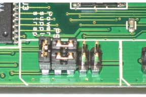
- Verify the jumper pins on the PCB and configured as shown below.
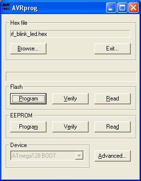
- Program both radios with the
rf_blink_led.hexfile using the programming instructions below. The file is found in the “CC2420DBK Examples Release”, available on the CC2420 product page on Chipcon.com. - On the first radio, press and release the ‘RESET’ button (S1), then push the mini joystick (U5) in any direction—up, down, left, or right—and release. Be careful not to press directly down on the mini joystick.
- On the second radio, press and release the ‘RESET’ button (S1), then press and release the mini joystick (U5) directly down like a push-button.
- Turn the potentiometer on either of the radios and it will adjust the brightness of an LED on the other board.
Step 3: Programming a HEX File on the CC2420DBK
Follow these steps to program the CC2420DBK radio board with a compiled HEX file. Refer to page 43 of the CC2420DBK Demonstration Board Kit User Manual for more information.
- Power the CC2420DBK radio board using an external 4-10V power supply or a 9V battery.
- Connect the CC2420DBK serial port to your PC serial port using the supplied cable.
- Hold down the ‘S2’ push button on the radio.
- Press and release the ‘RESET’ (S1) button while still holding the ‘S2’ button to enter the programming mode.
- Release the ‘S2’ button. All LEDs should be off.
- Start up AVR Studio 4, and select Tools → AVR Prog…
- Browse to find your
*.hexfile. Userf_blink_led.hexfound in the “CC2420DBK Examples Release” for testing the wireless link. - Click on the Flash “Program” button to program the Flash memory.
- Push the ‘RESET’ (S1) button on the radio to exit programming mode and start your application.
Step 4: Create an AVR Studio Project
Now you can create your own project within AVR Studio and begin writing code for the radio board. Begin by compiling the ‘rf_blink_led.c’ file and programming the radios with the compiled *.hex file. Then verify the wireless link still works, as in the wireless link test above.
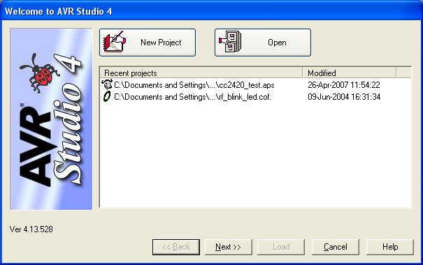
- Launch AVR Studio 4, and open the Project Wizard from Project → Project Wizard. By default the Project Wizard launches at startup.
- Click on ‘New Project.’
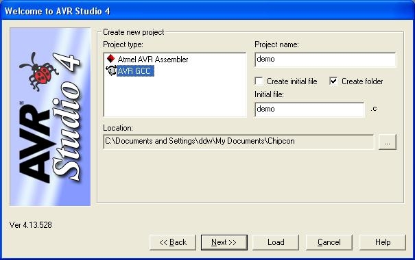
Select ‘AVR GCC’ and give the project a name. Uncheck ‘Create initial file’, and check ‘Create folder.’ Browse to the location where you would like the project to be stored. Click ‘Next’.
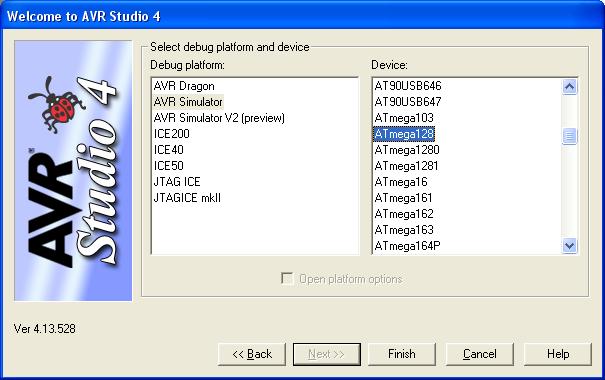
Select ‘AVR Simulator’ as the Debug platform, and ‘ATmega128’ as the Device. Click ‘Load’.
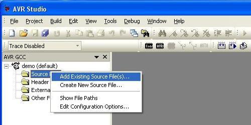
Right-click on the ‘Source Files’ folder and add the following existing source files to the project. These files are available in the “CC2420DBK Libraries” from the CC2420 product page on Chipcon.com.
lib/basic_rf/basic_rf_init.c
lib/basic_rf/basic_rf_receive.c
lib/basic_rf/basic_rf_send_packet.c
lib/hal/hal_rf_set_channel.c
lib/hal/hal_rf_wait_for_crystal_oscillator.c
lib/hal/atmega128/hal_wait.c
- Copy the following file to your project directory and the right-click on the ‘Source Files’ folder and add the file to the project. This file is available in the “CC2420DBK Examples Release” from the CC2420 product page on Chipcon.com.apps/basic_rf/rf_blink_led/rf_blink_led.c
- Your project should now look like this.

- Double click on the
rf_blink_led.cunder Source Files to view the file. This contains the main program routine, and is the template you should use to begin your own project. - Right click on the project name and select ‘Edit Configuration Options.
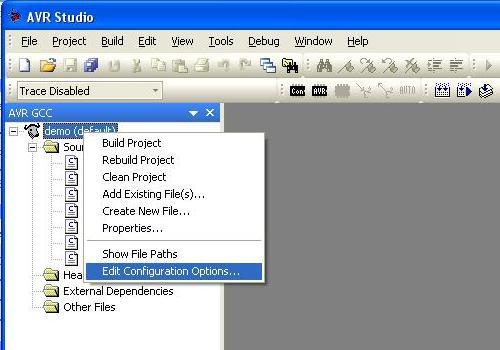
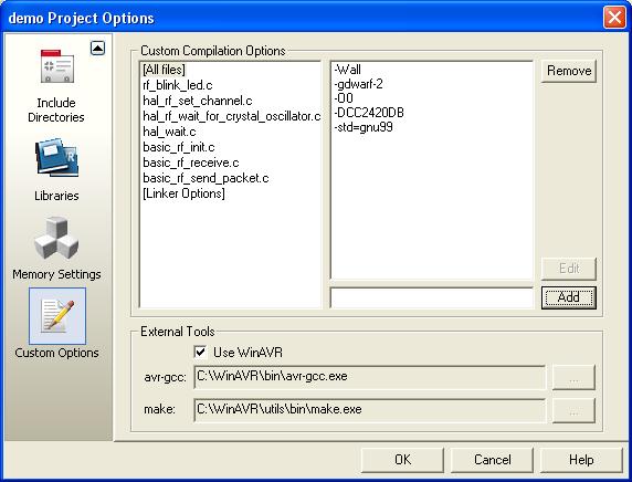
Select ‘Custom Options,’ and add the following two options in the ‘Custom Compilation Options’ add field and click ‘OK’.
-DCC2420DB
-std=gnu99
Make sure to include the dashes.
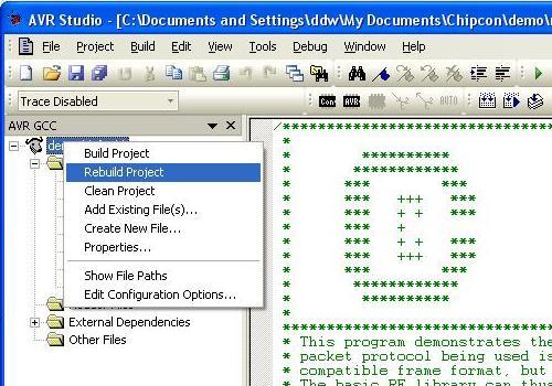
Build the project by right clicking on the project name again, and selecting ‘Rebuild.’ A *.hex file should now be created in the [project_directory]/default/ directory that you can program the radio with following the programming steps outlined above. Compile the rf_blink_led.c source without modification first and program the radios with the generated *.hex file to verify everything is working. This is the same demo used to test the wireless link above.
Source: CC2420 Radio
- How do I verify the wireless link is working properly?
Power both boards, program them with rf_blink_led.hex, press RESET then move the joystick on one board and press the joystick down on the other; turning a potentiometer on one adjusts an LED on the other. - What software is required to install for this project?
You must install WinAVR, AVR Studio 4, and download the CC2420DBK Examples Release and Libraries from Chipcon's website. - Can the CC2420DBK be powered by a battery?
Yes, the board can be powered by a 9V battery or an external supply between 4-10V. - What are the data rate specifications for the radio?
The radio operates at a maximum data rate of 250kb/s, though the realistic average including overhead is closer to 25kb/s. - How do I enter programming mode on the radio board?
Hold down the S2 push button while pressing and releasing the RESET (S1) button, then release S2 when all LEDs turn off. - Which specific source files must be added to the AVR Studio project?
Add basic_rf_init.c, basic_rf_receive.c, basic_rf_send_packet.c, hal_rf_set_channel.c, hal_rf_wait_for_crystal_oscillator.c, hal_wait.c, and rf_blink_led.c. - What custom compilation options must be set in AVR Studio?
Add -DCC2420DB and -std=gnu99 to the Custom Compilation Options field. - Does the development kit include SmartRF Studio software?
No, you do not need the Chipcon SmartRF Studio software for this project. - What is the function of the potentiometer on the board?
Turning the potentiometer adjusts the brightness of an LED on the paired radio board during testing. - Where should the include directory contents be copied after downloading libraries?
Copy the contents of the 'include' directory to C:WinAVRavrinclude.