Summary of Clock-Free Arduino: Maximizing ATmega328 Performance
This article explains how to create a minimal Arduino UNO on a breadboard using an ATmega328p microcontroller running on its internal 8 MHz oscillator, eliminating the need for an external 16 MHz crystal oscillator. It covers installing support hardware configurations in the Arduino IDE, burning the bootloader using an ArduinoISP programmer, and programming the ATmega328 either with an Arduino or an FTDI USB-to-serial adapter. The minimal setup reduces power consumption and suits low-demand projects like irrigation or solar tracking. Included is an ArduinoISP sketch for turning an Arduino into an AVR ISP programmer.
Parts used in the Minimal Arduino UNO on a Breadboard:
- ATmega328p microcontroller
- Breadboard
- Arduino board (for programming as ISP)
- FTDI USB to Serial adapter (FT232RL breakout board)
- Resistors for LEDs (heartbeat, error, programming)
- LEDs for debug indication
- Wires/jumpers
- 5V power source (USB or battery)
- USB mini type-B cable (for FTDI adapter)
While most opt for a 16MHz oscillator in a DIY Arduino setup, it’s intriguing to discover that the ATmega328 can function without it.
An Arduino typically comprises various elements such as a linear regulator, USB to Serial microcontroller, debug LED, power LED, reset button, RX & TX LED, crystal oscillator, among others. However, a minimal configuration can solely involve the core of the Arduino UNO, specifically the ATmega328p microcontroller, aiming to decrease Arduino’s power consumption. This project can be viewed as an extended iteration of that minimalistic approach.
Making a Minimal Arduino UNO on a Breadboard
Many individuals have found success in crafting a simplified Arduino setup, typically incorporating a 16 MHz crystal. However, it’s possible to eliminate this crystal along with the accompanying 22 pF capacitors. Instead, you can configure the ATmega328 to rely on its internal 8 MHz RC oscillator as the primary clock source.
Install Support for Hardware Configuration
Download the hardware configuration archive labeled breadboard-1-6-x.zip, Breadboard1-5-x.zip, or Breadboard1-0-x.zip, depending on the Integrated Development Environment (IDE) you are using.
Inside your Arduino sketchbook folder (you can locate its location in the Arduino preferences dialog), create a new folder named “hardware.” If you’ve previously installed additional hardware configurations, you might already have a “hardware” folder within your sketchbook.
Extract the contents of the breadboard folder from the downloaded zip archive and move it into the “hardware” folder in your Arduino sketchbook.
Restart the Arduino software for the changes to take effect.
Navigate to the Tools > Board menu, where you should now see “ATmega328 on a breadboard (8 MHz internal clock)” as an option.
Once these steps are completed, you’ll be able to burn the bootloader and upload programs onto your ATmega328.
Putting Stuff on Breadboard
Certainly! Here’s a rephrased version that incorporates the previously listed information and includes a pin mapping of the ATmega328P:
Ensure you have all the aforementioned elements. Additionally, have a pin mapping reference for the ATmega328P readily available while setting up the circuit.
Using ATmega Without UNO Bootloader
Firstly, if you’ve acquired a blank microcontroller lacking a bootloader, the initial step is to burn the bootloader onto the ATmega chip to enable programming functionality.
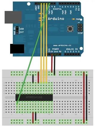
Next, consult the schematics and position the ATmega chip onto the breadboard.
Proceed by launching the ArduinoISP firmware found in the Examples section onto your Arduino board.
In the Tools menu, choose the appropriate items from the Board and Serial Port menus that correspond to the programmer board (not the board to be programmed).
Upload the ArduinoISP sketch onto the board.
When burning the bootloader, ensure you’ve selected “ATmega328 on a breadboard (8MHz internal clock)” from the Tools > Board menu.
In the Tools > Programmer menu, designate the Arduino as ISP.
Utilize the Burn Bootloader command found in the Tools menu.
If you’ve completed step 1, you can skip step 2.
2. Using ATmega with UNO boot-loader
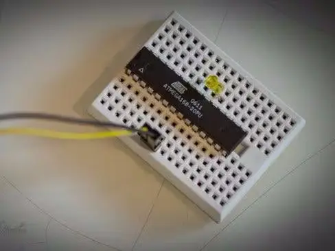
If the ATmega has been preloaded with the bootloader, simply place it onto the breadboard, and we can begin programming the ATmega328p microcontroller.
3. Programming the ATmega chip (using other Arduino)
Remove the microcontroller from the Arduino used as the programmer.
Refer to the schematics and pin assignments, linking the programmer Arduino’s Rx and Tx to the breadboard Arduino’s Tx and Rx respectively.
Establish a connection between the RESET pins of both the programmer Arduino and the breadboard Arduino.
Connect the GND and VCC pins of the breadboard Arduino to the corresponding pins on the programmer Arduino.
Navigate to Tools > Board menu and ensure selection of “ATmega328 on a breadboard (8MHz internal clock).”
Verify the port and click “upload.”
Disconnect the connections, enabling the use of a battery to power the setup for several months, depending on the nature of the project.
4. Programming the ATmega chip (using FTDI USB to Serial Adapter)
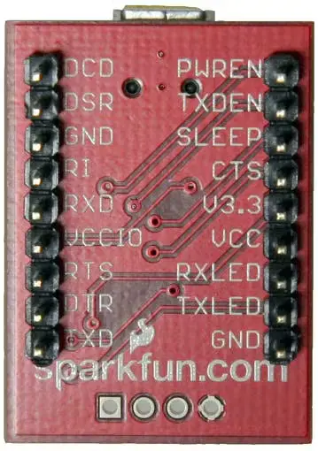
Wondering about the functionalities of the pin outs on the FT232RL breakout board? Just turn it over! For this scenario, I’ll utilize VCC (to provide 5V from the USB port to your board), GND, TXD, and RXD. [Consult the schematics for details]
This board is typically sold without headers. To use it, solder the male headers and place it onto the breadboard.
Connect the Rx pin of the ATmega chip to the Tx pin of the board, and the Tx pin of the ATmega chip to the Rx pin of the board.
Ensure to connect Vcc and GND to the power rails on the breadboard.
Plug in a USB mini type – B cable and connect it to your computer. Upload your sketch using the Arduino IDE. Remember to select “ATmega328 on a breadboard (8MHz internal clock)”.
Initially powered by USB, once disconnected, you can supply power by connecting the battery terminals to the breadboard’s power rails.
Caution: It’s advisable to utilize an Arduino with an internal 8 MHz clock if your project doesn’t demand the execution of numerous commands within a very brief timeframe. These internal clocks are suitable for projects involving minimal ongoing work over extended periods, such as water irrigation or solar tracking systems.


