Summary of Configuring and using XBEE wireless modules
This article describes a DIY project to create a breadboard-friendly PCB adapter for XBee wireless modules, converting their 2.0mm pin spacing to standard 2.54mm DIP spacing. It details the fabrication process using Eagle software and soldering techniques, while explaining basic XBee configuration defaults like 9600bps baud rate and PAN ID 3332. The guide also warns about voltage tolerance issues and lists necessary hardware components for interfacing.
Parts used in the XBee Breadboard Adapter:
- Xbee wireless modules
- Berg strip (broken into four 10-pin parts)
- USB to serial converter
- IC 7404 (Inverter)
- 5V regulator (7805)
- 3.3V regulator (LD33V or LM3940) or LM317T
Xbees are some of the most powerful wireless modules you can find and they’re also very easy to configure and use. The only thing is they cost about Rs.1000 to Rs.2500 depending on the range and other parameters. If you’re like me and only bought the modules without the breakout boards or forgot to buy it, then you have to make the modules breadboard friendly to use it. I’ve made a PCB which converts the 2.0mm spacing of the pins of xbee to the normal DIP spacing of 2.54mm.
You can download the schematic and board files of eagle here. If you don’t have eagle you can download the layout in pdf format here.
You need to make two PCB’s, one for each module. If you don’t know how to make PCB’s check out my tutorial which shows you how to easily make PCB’s at home.
PCB’s after etching and drilling.
Now take a berg strip and break it into 4 parts with 10 pins each and push the pins to one side as shown.
To do this just put the strips on the PCB and push them against the ground and they’ll go inside.
Now put the 2.0mm strips and solder everything. Remember that since this is a single sided PCB, you have to solder the berg strip from the bottom. This will seem a little awkward but it saves you the need for a double sided PCB.
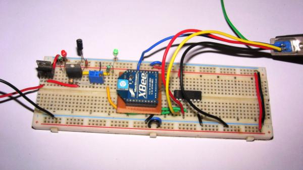
So now that we’ve made a breadboard friendly module, it’s time to configure them. Xbees come configured out of the box if you just want to use it as a UART serial link, they’re configured at 9600bps and their PAN(Personal Area Network) ID is set to 3332. Devices with same PAN ID can “see” each other i.e. they’re in the same network. But xbees can be used for so much more, e.g. you can directly use the built in ADC to sample values and send it directly without any microcontroller. There are also 8 digital I/O pins which you can configure as air wires.
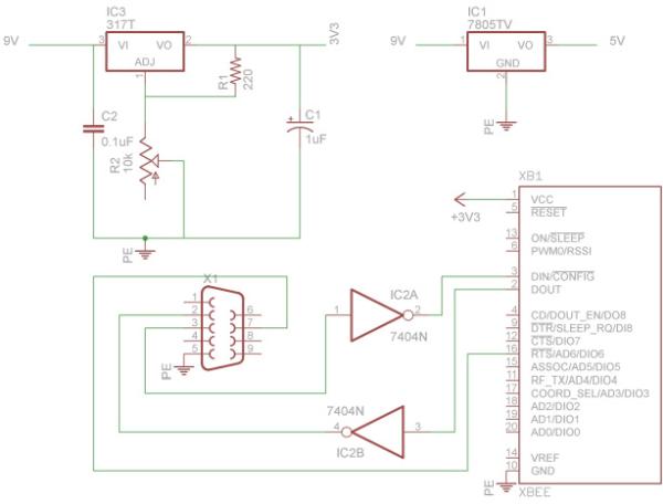
Before you begin to do connect anything, please note that the VCC on xbee is not 5V tolerant, so if you’ve given 5V to the VCC, you might’ve already fried it. Most users say that the input lines are also not 5V tolerant but it seems to work fine for me. Components required:
- Xbee wireless modules
- USB to serial converter(if you don’t have a serial port)
- IC 7404(Inverter)
- 5V regulator (7805)
- 3.3V regulator(LD33V or LM3940), alternately you can use a LM317T to get 3.3V which is what I did.
Software required.
Read More: Configuring and using XBEE wireless modules
- What is the main purpose of the PCB described in the article?
The PCB converts the 2.0mm pin spacing of XBee modules to the normal 2.54mm DIP spacing to make them breadboard friendly. - How can I download the design files for this project?
You can download the schematic and board files in Eagle format or the layout in PDF format from the provided links. - Can I use a double-sided PCB for this project?
No, the author uses a single-sided PCB by soldering the berg strip from the bottom to avoid the need for a double-sided board. - What are the default configuration settings for new XBee modules?
New modules come configured at 9600bps with a PAN ID set to 3332. - Is the VCC pin on an XBee module 5V tolerant?
No, the VCC on the XBee is not 5V tolerant, and applying 5V may fry the module. - What components are required to configure the XBee modules?
Required components include XBee wireless modules, a USB to serial converter, IC 7404, a 5V regulator, and a 3.3V regulator. - Can XBee modules function without a microcontroller?
Yes, you can directly use the built-in ADC to sample values and send them without any microcontroller. - How many digital I/O pins are available on the XBee modules?
There are 8 digital I/O pins which can be configured as air wires.