Summary of Connecting a 16×2 LCD to an ATmega32 AVR Microcontroller in 4-bit mode
This article details the integration of a 16x2 LCD with an Atmega32 microcontroller using 4-bit communication mode. It covers hardware specifications, pin configurations, and provides complete AVR C code for initialization, command sending, and character display functions within the Atmel Studio environment.
Parts used in the Atmega32 and 16x2 LCD Project:
- Atmega32 microcontroller
- 16x2 LCD module
- 7066 or equivalent built-in controller
- 5V power supply
- Ground connection
- Contrast adjustment (VEE)
- Backlight Anode (+) and Cathode (-)
- Data pins D0 through D7
- Control pins RS, RW, and EN

Greetings, everyone! I’m here today to share a fascinating and straightforward method for connecting a 16×2 LCD to the Atmega32 microcontroller and writing the necessary code for it.
I employed a 16×2 LCD module. The acronym “LCD” stands for “liquid crystal display,” a type of electronic display module utilized in a wide array of devices such as mobile phones, calculators, computers, television sets, and more. These displays are particularly favored for their versatility in showcasing multi-segment light-emitting diodes and seven-segment characters. The primary advantages of using this module include cost-effectiveness, ease of programmability, support for animations, and the absence of restrictions when it comes to displaying custom characters, special symbols, and animations, among other features.
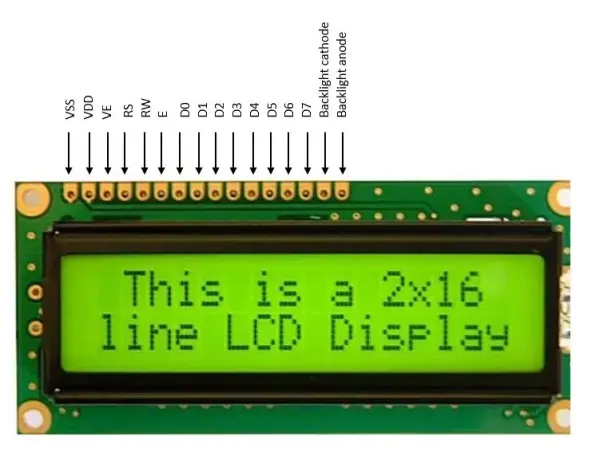
The display features a total of 16 pins. These pins encompass 8 data pins, labeled D0 through D7, as well as 3 control pins known as RS, RW, and EN. The remaining 5 pins serve the purpose of providing power and controlling the backlight of the LCD. In the 4-bit mode, data and commands are transmitted in a 4-bit format, with only 4 of the data pins (D4 through D7) connected to the microcontroller. The EN line, referred to as ‘Enable,’ serves as a control line that informs the LCD when the microcontroller is transmitting data to it or ready to receive data from the LCD. The RS line is denoted as the “Register Select” line. Lastly, there is the RW control pin, which stands for Read/Write. When RW is at a low state (0), it signifies that data on the data bus is being written to the LCD. Conversely, when RW is set to a high state (1), the program is effectively making queries to the LCD.
VCC - connect to 5V
VSS - connect to ground
VEE - contrast adjustment
RS - register select 0:command, 1:data
RW - read/write 0:write 1:read
EN - Enable, falling edge trigged
D0-D7 - Data pins
A/LED+ - Back-light Anode(+)
K/LED- -Back-light Cathode(-)
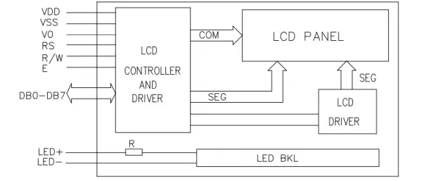
The LCD module is equipped with 16 columns and 2 rows, resulting in a total capacity of 32 characters, with each character comprised of 5×8 pixel dots. It operates at a voltage of 5.0V with a current consumption of 1.6mA. The duty cycle is set at 1/16, and it features a built-in controller, specifically the 7066 or an equivalent model. The operational temperature range spans from 0 to 50°C. This module can function in both 8-bit and 4-bit communication modes, but in my implementation, I utilized the 4-bit mode, which makes use of only 4 data lines. The concept of 4-bit communication is introduced to conserve the microcontroller’s pins.
The internal configuration of the LCD
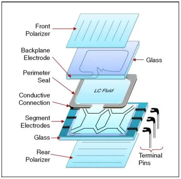
An LCD panel comprises multiple layers, with the front polarizer being a critical component. The front polarizer is situated on the exterior of the upper glass layer, which also provides structural support for the LCD panel. Beneath the upper glass layer, there is a transparent coating of Indium Tin Oxide (ITO) on its lower surface. ITO is conductive and serves as the backplane or the common electrodes for the LCD panel. The patterns created by the backplane and segment ITO define the display content, such as numbers, letters, symbols, icons, and so on…
The alignment of polyimide on the lower glass layer is perpendicular to that on the upper glass layer, resulting in a twist in the liquid crystal (LC) fluid. The subsequent layer consists of a polyimide coating on the lower glass, followed by the ITO segment electrodes. Finally, the rear polarizer is affixed to the external surface of the lower glass. The polarization axis of the rear polarizer may align with the front polarizer, or it may be phase-shifted by 90 degrees, depending on the LCD panel’s viewing mode.
LCD Display Specifications
• Input Voltage – 5.0 V
• Supply Current – 1.0 mA (without backlight)
• Display format – 16*2 characters
• Duty Cycle – 1/16
• System Interface – 4 bit or 8 bit
• 5*8 dots include cursor
• Built – in – controller: ST 7066 (or equivalent)
• Operating Temperature 0-50℃
• Storage Temperature -10℃ − 60℃
Operations within the LCD.h File
#ifndef LCD_H_#define LCD_H_
#include <avr/io.h>
#define F_CPU 8000000UL
#include <util/delay.h>
#define LCD_CMD_CLEAR_DISPLAY              0x01
#define LCD_CMD_CURSOR_HOME               0x02// Display control
#define LCD_CMD_DISPLAY_OFF                0x80
#define LCD_CMD_DISPLAY_NO_CURSOR          0x0c
#define LCD_CMD_DISPLAY_CURSOR_NO_BLINK    0x0E
#define LCD_CMD_DISPLAY_CURSOR_BLINK       0x0F// Function set
#define LCD_CMD_4BIT_2ROW_5X7              0x28
#define LCD_CMD_8BIT_2ROW_5X7              0x38//LCD DATA AND CONTROL PORTS
#define   DATA_BUS        PORTA
#define   CTL_BUS       PORTB
#define   DATA_DDR       DDRA
#define   CTL_DDR       DDRB//LCD DATA PINS
#define   LCD_D4      4
#define   LCD_D5      5
#define   LCD_D6      6
#define   LCD_D7      7// LCD CONTROL PINS
#define   LCD_EN      3
#define   LCD_RW      2
#define   LCD_RS      1//functions prototype
void lcd_init(void);
void lcd_send_command (uint8_t );
void lcd_write_character(uint8_t );
void lcd_write_word(uint8_t[]);
void lcd_clear(void);
void lcd_set_courser(uint8_t,uint8_t);
void lcd_goto_xy (uint8_t , uint8_t );
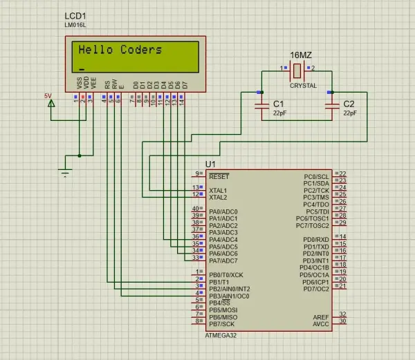
Circuit diagram
Atmel Studio C code
#include "lcd2.h"/*
*Function name  : lcd_init
*Parameters     : void
*return       : void
*purpose        : initialize LCD pins as output
*       and setting up the operation mode(4-bit)
*      default setting (cursor on)
*/
void lcd_init(void)
{
DATA_DDR = (1<<LCD_D7) | (1<<LCD_D6) | (1<<LCD_D5)| (1<<LCD_D4);
CTL_DDR |= (1<<LCD_EN)|(1<<LCD_RW)|(1<<LCD_RS);
DATA_BUS = (0<<LCD_D7)|(0<<LCD_D6)|(1<<LCD_D5)|(0<<LCD_D4);
CTL_BUS|= (1<<LCD_EN)|(0<<LCD_RW)|(0<<LCD_RS);_delay_ms(5);
CTL_BUS &=~(1<<LCD_EN);
_delay_ms(5);lcd_send_command(LCD_CMD_4BIT_2ROW_5X7);
/*2
 line,5*7 matrix in 4-bit mode*/_delay_ms(5);
lcd_send_command(LCD_CMD_DISPLAY_CURSOR_BLINK);
 /*Auto Increment cursor*/
_delay_ms(5);lcd_send_command(0x80);
 /*
display off*/
}/*
*Function name  : lcd_send_command
*Parameters: uint8_t command
*return: void*purpose: sending a command to LCD by sending
*       the first nibble then the second nibble
*      enabling and disabling the LCD in between
*/
void lcd_send_command (uint8_t command){DATA_BUS=((command&0b11110000));
 /*Sending upper nibble
*/
CTL_BUS &=~(1<<LCD_RS);
 /*RS=0, command reg
*/
CTL_BUS |=(1<<LCD_EN);
   /*Enable pulse*/
_delay_ms(5);
CTL_BUS &=~(1<<LCD_EN);
_delay_ms(5);
DATA_BUS=((command&0b00001111)<<4);
 /*Sending lower nibble*/
CTL_BUS |=(1<<LCD_EN);
_delay_ms(5);
CTL_BUS &=~(1<<LCD_EN);
_delay_ms(5);}/*
*Function name  : lcd_write_word
*Parameters     : uint8_t word[20]
*return       : void
*purpose        : printing a full word to the
*       LCD (Maximum 20 characters)
*/
void lcd_write_word(uint8_t word[20])
{
int i=0;while(word[i]!='\0')
{
lcd_write_character(word[i]);i++;
}
}/*
*Function name  : lcd_write_character
*Parameters: uint8_t character
*return: void
*purpose: sending one character to LCD by sending
*        the first nibble first then the second nibble
*       enabling and disabling the LCD in between
*/
void lcd_write_character(uint8_t character)
{
DATA_BUS=((character & 0b11110000));
CTL_BUS|=(1<<LCD_RS);
CTL_BUS |=(1<<LCD_EN);
_delay_ms(5);
CTL_BUS &=~(1<<LCD_EN);
_delay_ms(5);
DATA_BUS=((character & 0b00001111)<<4);
CTL_BUS |=(1<<LCD_EN);
_delay_ms(5);
CTL_BUS &=~(1<<LCD_EN);
_delay_ms(5);
}
/*
*Function name  : lcd_clear
*Parameters     : void
*return       : void
*purpose        : Clearing the LCD screen by sending
*      the LCD_CMD_CLEAR_DISPLAY command to LCD
*/
void lcd_clear(void){lcd_send_command(LCD_CMD_CLEAR_DISPLAY);
_delay_ms(5);
}
void lcd_goto_xy (uint8_t line,uint8_t pos)
//line = 0 or 1{lcd_send_command((0x80|(line<<6))+pos);_
delay_us (50);
}
int main(void)
{
/*
 Replace with your application code */
lcd_init();_delay_ms(20);lcd_init();
_delay_ms(20);
lcd_write_word("Hello Coders"); //Display "Not Registered"
_delay_us(20);
lcd_goto_xy(1,0);
lcd_clear();
_delay_ms(20);}
The function “lcd_init”: This function serves as the initialization process for the LCD. It includes a power-on delay, which waits for 5ms. It proceeds to transmit the 0x28 command to initialize a 2-line 5×8 matrix for the LCD operating in 4-bit mode and a 16×2 configuration. The 0x0c command is then sent to turn on the display. Consequently, the LCD is prepared to receive data for presentation.
The “lcd_send_command” function: Initially, it transmits the high nibble of the command. Following this, it sets the RS and RW pins to low and generates a high-to-low pulse on the Enable (E) pin. Subsequently, it sends the lower nibble of the command. At this point, the command value can be dispatched to the LCD data port.
lcd_write_character function: When we apply an enable pulse, the LCD captures the existing data and showcases it on a 5×8 matrix since RS serves as a data register.
lcd_write_word function:This function accepts a string and transmits each character individually to the LCD data function until the string’s conclusion. It employs a while loop to dispatch one character during each iteration, with a null character signifying the string’s end.
lcd_clear function: This operation will erase the display content and reposition the cursor to the (0,0) position.
- How is the LCD connected in 4-bit mode?
In 4-bit mode, only data pins D4 through D7 are connected to the microcontroller to conserve pins. - What voltage does the LCD module operate at?
The LCD module operates at an input voltage of 5.0V. - Does the RW pin control reading or writing?
When RW is low (0), data is written to the LCD; when high (1), the program queries the LCD. - What is the purpose of the RS line?
The RS line acts as Register Select, where 0 indicates a command and 1 indicates data. - Can the LCD display custom characters?
Yes, the module supports displaying custom characters, special symbols, and animations without restrictions. - What command initializes the 2-line 5x8 matrix in 4-bit mode?
The command 0x28 initializes the 2-line 5x8 matrix for the LCD operating in 4-bit mode. - How does the lcd_clear function work?
The lcd_clear function erases the display content by sending the LCD_CMD_CLEAR_DISPLAY command and repositions the cursor to (0,0). - What is the duty cycle of the LCD panel?
The duty cycle is set at 1/16.