Using PWM (Pulse Width Modulation) to control a device is a common practice in embedded systems; for example, you can use it to control the light intensity of a LED or control the speed of a DC motor.
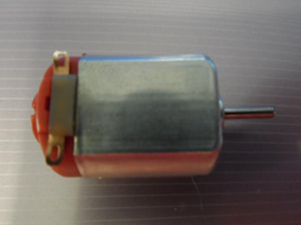
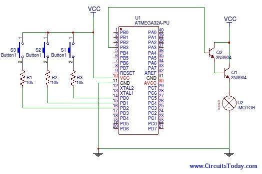
In this article, we will explain how to get a PWM from the AVR Atmega32 and we shalll apply the output PWM to a small DC motor to vary its speed.
In order to get the PWM from AVR, we need to use the timer/counter module of the AVR. This module can be used in several modes to generate different PWM signals of different characteristics; here we shall explain how to use the counter in the “Phase Correct PWM” mode. Atmega32 has 3 timer/counters and we are using timer/counter 0.
In “Phase Correct PWM” mode, the counter counts repeatedly from 0 to its maximum value (0xFF) and then back from the maximum to zero. The Output pin (OC0) is cleared when the counter reaches a certain value called the “Compare value” while up counting, and is set when the counter reaches the same value while down counting. This compare value is set by the software in a register called OCR0 (Output Compare Register), while the value of the counter itself is contained in a register called TCNT0.
When the value of TCNT0 matches the OCR0, it’s called a Compare Match.
You can also invert the output PWM by changing the values of bits (COM00 and COM01) in the TCCR register. In that case, the Output pin (OC0) is set when compare match occurs while up counting, and is cleared when compare match occurs while down counting, and the waveform will be as shown in the timing diagram below.
Let’s get first to configuring the PWM, this is done in 2 simple steps:
- Configure the TCCR0 register.
- Set the compare value in the OCR
-
Configuring the TCCR0 Register
- Set bits WGM00 and WGM01 to 1 and 0 respectively. This enables the phase correct PWM mode.
- Set bits COM00 and COM01 to 0 and 1 respectively. This means that the generated PWM will be an inverted PWM.
- Set bits CS00 and CS01 and CS02 to 1, 0 and 1 respectively. This means that the counter will be clocked from the system clock divided by 1024.
Read More: How to control DC motor speed using PWM on Atmega32