Summary of Wooden Digital Clock is controlled over WiFi
This article details the construction of a compact wooden digital clock featuring time, temperature, humidity, alarm, and WiFi control via a web browser. The 64x64x79 mm device uses PLA with wood veneer and includes a vibration sensor to stop alarms. The build involves two custom PCBs: one for the MAX7219-driven display and another for the STM8S005C6T6 microcontroller paired with an ESP8266-12 module. Firmware is uploaded using STVP-STM8 software and an ST-LINK programmer.
Parts used in the Wooden Digital Clock:
- CEM3491BY 4-Digit 7-Segment Display
- MAX7219 LED Driver
- 10k Resistor
- 10uF Capacitor
- XH2.54-5P Connector
- STM8S005C6T6 Microcontroller
- ESP8266-12 WiFi Module
- ASM1117-5.0 Voltage Regulator
- ASM1117-3.3 Voltage Regulator
- 470uF Capacitor
- 1uF Capacitor
- 4.7k Resistors
- Mini Pushbutton Switch
- SW-420 Vibration Sensor
- DS1307 Real Time Clock
- 32.768 kHz Crystal
- CR2032 Battery and Holder
- XH2.54-2P and XH2.54-4P Connectors
- Cable Double Connectors
Wooden Digital Clock with
– Time, Temperature, Humidity, Alarm

– WiFi controller through web browser
– Advance display config
– Stop alarm by vibration sensor
size : 64 x 64 x 79 mm
i use PLA with wood veneer instead of full wood
my room’s too small for put woodworking tools
If want view detail all steps, you can watch video
– Time, Temperature, Humidity, Alarm
– WiFi controller through web browser
– Advance display config
– Stop alarm by vibration sensor
size : 64 x 64 x 79 mm
i use PLA with wood veneer instead of full wood
my room’s too small for put woodworking tools
If want view detail all steps, you can watch video
Step 1: PCB – Display
This step for make PCB (two layer) display module (if cannot do, you can find PCB Manufacturing Service)
I use MAX7219 for led driver and display with Led CEM3491, it have two dots for sec and upper dot for temperature
But CEM3491 is Common Anode, MAX7219 for drive Common Cathode, so must reverse pin Digit and Segment
Material list :
– (x1) CEM3491BY (0.39″ Common Anode 4-Digit 7-Segment Display Amber Color)
– (x1) MAX7219 (Led driver display)
– (x1) 10k Resistor
– (x1) 10uF Capacitor
– (x1) XH2.54-5P (5Pin Straight PCB Male Box Header Bar Connector)
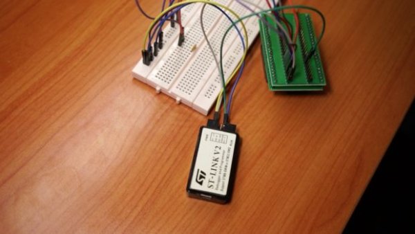
Step 2: Program
I have complete program firmware, you just upload it to STM8S005C6T6 by software STVP-STM8 with file controller.s19
STVP-STM8 : http://www.st.com/en/development-tools/stvp-stm8….
hardware for upload : ST-LINK
if see “PROGRAM MEMORY programming completed” it mean done
about upload firmware, view detail in video at 10:35
STVP-STM8 : http://www.st.com/en/development-tools/stvp-stm8….
hardware for upload : ST-LINK
if see “PROGRAM MEMORY programming completed” it mean done
about upload firmware, view detail in video at 10:35
Step 3: PCB – Controller
Next for solder microcontroller STM8S005C6T6 and other parts for complete PCB controller
button for reset wifi config, just hold down 3s and buzzer will fire beep sound
Material list :
– (x1) STM8S005C6T6 (Microcontroller)
– (x1) ESP8266-12 (WiFi module)
– (x1) ASM1117-5.0 (voltage regulators 5V)
– (x1) ASM1117-3.3 (voltage regulators 3V3)
– (x1) 470uF Capacitor
– (x1) 1uF Capacitor
– (x3) 10uF Capacitor
– (x2) 4.7k Resistor
– (x1) Mini Pushbutton Switch (4Pin)
– (x1) SW-420 (Vibration sensor)
– (x1) DS1307 (Real Time Clock)
– (x1) 32.768 khz crystal
– (x1) CR2032 battery
– (x1) CR2032 battery holder
– (x2) XH2.54-2P (2Pin Straight PCB Male Box Header Bar Connector)
– (x1) XH2.54-5P (5Pin Straight PCB Male Box Header Bar Connector)
– (x1) XH2.54-4P (4Pin Straight PCB Male Box Header Bar Connector)
– (x2) Cable Double Connector XH2.54-2P
– (x1) Cable Double Connector XH2.54-5P
– (x1) Cable Double Connector XH2.54-4P
Read more: Wooden Digital Clock is controlled over WiFi
- How do I configure the WiFi settings?
Hold down the reset button for 3 seconds until the buzzer beeps. - Can I view the step-by-step video guide?
Yes, the author provides a video link to watch all detailed steps. - What material is used for the case instead of full wood?
The project uses PLA printed with a wood veneer finish due to limited space for tools. - Does the clock have an alarm feature?
Yes, it includes an alarm that can be stopped by a vibration sensor. - What software is required to upload the firmware?
You must use STVP-STM8 software to upload the controller.s19 file. - Which hardware tool is needed to program the microcontroller?
An ST-LINK programmer is required to upload the firmware. - What type of display driver is used in this project?
A MAX7219 driver is used with a CEM3491 Common Anode display. - How does the system keep track of time when power is off?
A DS1307 Real Time Clock powered by a CR2032 battery maintains the time. - What is the size of the finished clock?
The dimensions are 64 x 64 x 79 mm. - Can I buy the PCBs pre-made if I cannot make them?
Yes, you can find a PCB Manufacturing Service if you cannot fabricate the two-layer boards yourself.