
Summary of Interfacing Ultrasonic Rangefinder with AVR MCUs – AVR Tutorial
This article discusses ultrasonic range finder modules as a superior solution for distance measurement compared to IR or LED/LDR sensors. It highlights their wide operating range (1cm to 400cm), accuracy, and suitability for robotics, radar, and speed detection. The text details the physics of ultrasonic waves, explaining why their slower speed allows microcontrollers to measure time accurately, and provides a step-by-step guide on interfacing the module with a microcontroller via a single signal pin.
Parts used in Ultrasonic Range Finder Project:
- Ultrasonic Transmitter (Tx)
- Ultrasonic Receiver (Rx)
- Microcontroller Unit (MCU)
- Timer
- Stepper motors
- Servo motors
- Variable resistor (for comparison with older sensor types)
Obstacle detecting sensors are one of the most basic type of sensors that electronic hobbyists use. There are several methods to make cheap obstacle sensors. These simple sensors are made using a IR Rx/Tx pair or Normal LED and LDR pair(this design is most basic and is heavily affected by environment lighting conditions). These sensor may be useful for simple requirement but they have following drawbacks :-
- Can’t say anything about the real distance of obstacle.
- Give different result for different coloured obstacles.
- Need calibration (like setting up a variable resistor).
To solve these problems we have IR Range Finder Module (like one made by Sharp) but they have small range.
- Sharp GP2D12 Distance Measurement Sensor has a maximum range of 80cm
- Sharp GP2D120 Distance Measurement Sensor has a maximum range of 30cm only.
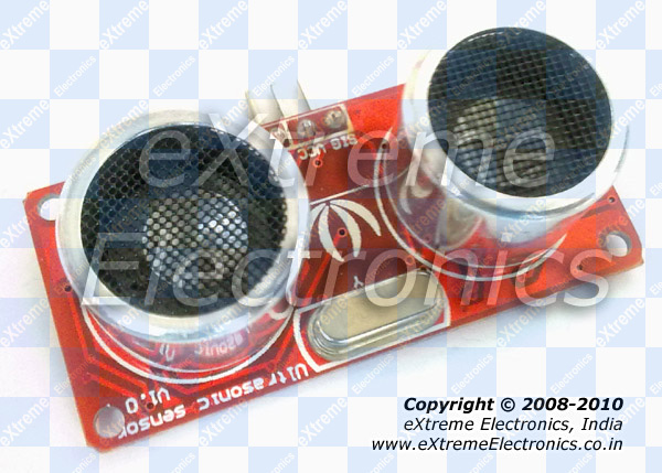
To solve all these problem we can use an Ultrasonic Range Finder Module. An Ultrasonic Range Finder Module uses ultrasonic waves (inaudible to humans) to measure distance. These module consist of an Ultrasonic Transmitter (Tx) that emits the ultrasonic wave, the waves after striking any obstacle bounces back and reach the Ultrasonic Receiver (Rx). By measuring the time it take for the whole process to complete and using simple arithmetic we can measure the distance to the obstacle. The Ultrasonic Range Finder Modules has a wide operating range of 1cm to 400cm with an accuracy of 1cm. These specifications makes it ideal for distance measurement application. These can be used for :-
-
- Contact less measurement of liquid level in tanks (even 4m deep tank!)
- Radars for robot.
- Obstacle sensing in Robotics.
- Speed check in roads.
- Handheld units that can be pointed on vehicles to measure their speed.
- Fixed unit installed in check booths that can click pictures of over speeding vehicles (Remember NFS Most Wanted?)
The reason for using ultrasonic wave are:-
- The speed of Ultra Sonic waves is 343m/s (Speed of Sound) which is not too fast for MCUs to measure accurately. Compare this with speed of electromagnetic waves (like light or radio waves) which is 30,00,00,000 m/s! So it takes only 20ns (nano second) to go and bounce back from an obstacle which is 3m away! An AVR running at 16MIPS(maximum for most AVRs) takes 62ns to execute a single instruction.
- Ultrasonic waves travels more narrow, like a beam than normal sound wave. This property helps the sensor detect the obstacles that are exactly in line with it only. The sensors can be rotated with steppers or servo motors to get a “image” of obstacle in the surrounding area (like a radar).
- Finally the wave do not disturb any humans nearby!
Ultrasonic Range Finder Interface.
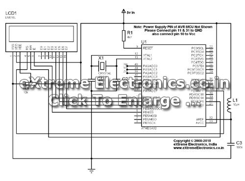
These modules are designed to be used for microcontroller based applications hence optimized for it. The interface is a single pin called SIG (signal). The MCU is connected to the Ultrasonic Range Finder Module by a single i/o line. The steps required to read distance are :-
- Microcontroller make the i/o line output. (by using the DDRx Register in AVR or TRISx Register in PIC)
- The i/o line is made low (this may be the default state of i/o pin)
- Wait for 10uS
- Make the i/o line high.
- Wait for 15uS
- Make the i/o line low
- Wait for 20uS
- Now make it input (by using the DDRx Register in AVR or TRISx Register in PIC)
- Module will keep it low. Wait till it is low, as soon as it becomes high start the timer.
- After that wait till it is high, as soon as it becomes low copy the timer value and stop the timer.
- Finally we have the time required for the wave to go hit the obstacle and come back to the module.
Read More: Interfacing Ultrasonic Rangefinder with AVR MCUs – AVR Tutorial
-
What are the main drawbacks of basic IR or LED/LDR obstacle sensors?
They cannot determine real distance, give different results for colored obstacles, and require calibration like setting up a variable resistor. -
How does an ultrasonic range finder measure distance?
It emits ultrasonic waves from a transmitter that bounce off an obstacle and return to a receiver; distance is calculated by measuring the time taken for this process. -
What is the operating range and accuracy of the ultrasonic module described?
The module has a wide operating range of 1cm to 400cm with an accuracy of 1cm. -
Why are ultrasonic waves preferred over electromagnetic waves for microcontroller applications?
Ultrasonic waves travel at 343m/s which is slow enough for MCUs to measure accurately, whereas light travels so fast it takes only 20ns to cover 3m. -
Can the sensor detect obstacles exactly in line with it?
Yes, because ultrasonic waves travel more narrowly like a beam than normal sound waves. -
How many pins are required to interface the module with a microcontroller?
The interface uses a single pin called SIG which connects to one i/o line of the MCU. -
What registers are mentioned for changing the i/o line state in AVR or PIC microcontrollers?
The DDRx Register is used for AVR and the TRISx Register is used for PIC microcontrollers.
