
Summary of Creating a charlieplexed LED grid to run on ATTiny85
This project demonstrates controlling 20 LEDs using a single ATTiny85 microcontroller via Charlieplexing, requiring minimal hardware. The author creates a 4x5 LED grid by wiring LEDs in both directions across five pins, utilizing bus-lines for connections and resistors for current limiting. Software defines pin configurations to activate specific LEDs while keeping others off, enabling complex simulations like Conway's Game of Life with just the microcontroller, LEDs, and resistors.
Parts used in the Charlieplexed LED Grid:
- ATTiny85 microcontroller
- 20 LEDs
- 5 resistors
- Power source
This instructable was inspired by my first AVR microcontroller project that I’ve been working on for some time now. I wanted to start learning more about the AVR microcontroller and see how much I could do with the minimum amount of hardware… no extra chips, simple components, etc… just my AVR and my code so I could experiment with a simple set of hardware.
I decided to start with one of the smallest AVRs available, the ATTiny85 with only 8 pins. With only 5 output pins available to me (using 6 would make me lose other chip functionality), I decided to experiment with Charlieplexing. Charlieplexing allows you to control many LEDs with very few output pins, by wiring up an LED in both directions to every possible pair-combination of the pins. In my case, 5 pins would allow control of up to 20 LEDs (5 x (5-1)). This would only require the ATTiny, LEDs, 5 resistors, and a power source.
More info on Charlieplexing: http://en.wikipedia.org/wiki/Charlieplexing
Step: 1 Planning out the wiring
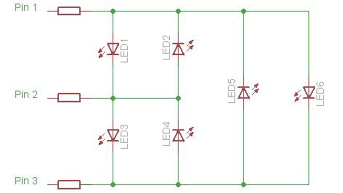
Conceptually, it’s not too difficult to understand how to wire up charlieplexing from some of the simpler diagrams available online (see diagram below courtesy of Wikipedia). However, I wanted to arrange 20 LEDs in a tight grid, and managing all the different connections & polarities seemed like it would get complicated as I scaled up from the 2 or 3 pin examples. Most importantly, to avoid mistakes when assembling, I wanted all my LEDs to be aligned the same direction on the board.
In the next step you’ll see how the wiring works out for a larger grid of LEDs.
Step: 2 Running bus-lines to all LEDs in the grid
After some thinking and sketching, I came up with my concept. In this project we’re working with 5 pins. Lets call them A, B, C, D and E.
Let’s just focus on pin A for a moment. If pin A is set to a positive voltage, it could control up to 4 different LEDs connected to ground on pins B through E. So I should have one line connecting the 4 positive ends (Anodes) of LEDs to pin A. This same concept extends to all the other pins. If Pin B was positive, it could control 4 others on pins A, C, D, and E. With this in mind, I planned out a positive “bus-line” for each column of 4 LEDs. These are shown in blue in the diagram below.
The negative (anode) connections can be handled on the other side of the board, as bus-lines between each row, feeding to LEDs on either side of the line as needed. These are shown in red in the diagram below.
All that’s left is to connect the respective bus-lines to each other so they all connect back to the same 5 pins. These connections are shown in green in the diagram below.
Finally, a resistor is placed between each line and the microcontroller to limit current through the LEDs.
While it’s a little complicated to solder by hand, it can be managed. Just go slowly and double check your connections as you go.
Step: 3 Charlieplexing in Software – getting started
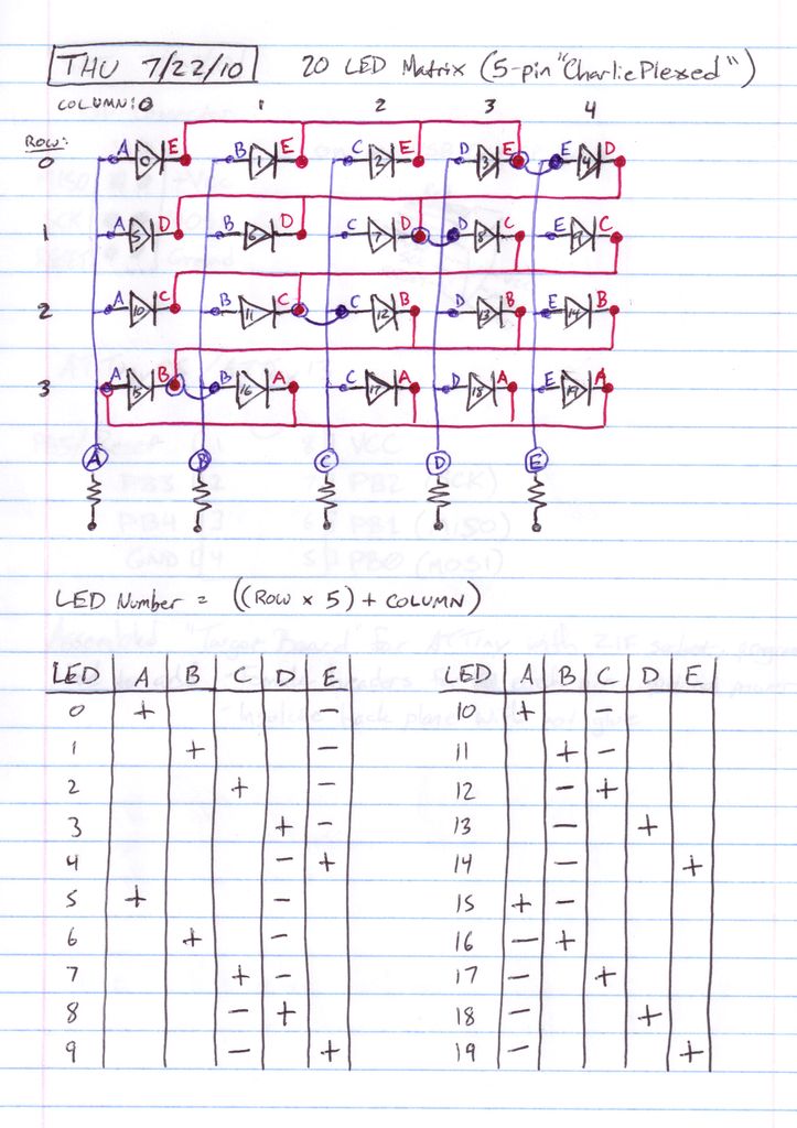
In my project, I used the 4×5 grid to run a Conways Game of Life simulation. However, before we get that complex, let’s cover some basics of the software to show how we light LEDs in this charlieplexed setup.
First, I’ve defined my pins A through E and specified which bit on PORTB they will be referring to. This makes it easier to refer to Line A through E later in the code:
#define LINE_A 0 //Pin 5 (PB0) on ATtiny85
#define LINE_B 1 //Pin 6 (PB1) on ATtiny85
#define LINE_C 2 //Pin 7 (PB2) on ATtiny85
#define LINE_D 3 //Pin 2 (PB3) on ATtiny85
#define LINE_E 4 //Pin 3 (PB4) on ATtiny85
In order to light any one of the 20 LEDs, we need to configure our 5 pins a different way for each LED. To light one LED, we need one pin set to an output with a high voltage, one pin set to an output with a ground voltage, and all the other pins need to be set to inputs to prevent current flow.
To make it simpler, we’ll set up some arrays to store all the configurations for DDRB (which sets the input/output modes of each pin) and PORTB (which sets the high/low voltage of each pin).
//DDRB direction config for each LED (1 = output)
const char led_dir[20] = {
( 1<<LINE_A | 1<<LINE_E ), //LED 0
( 1<<LINE_B | 1<<LINE_E ), //LED 1
( 1<<LINE_C | 1<<LINE_E ), //LED 2
( 1<<LINE_D | 1<<LINE_E ), //LED 3
( 1<<LINE_E | 1<<LINE_D ), //LED 4
( 1<<LINE_A | 1<<LINE_D ), //LED 5
( 1<<LINE_B | 1<<LINE_D ), //LED 6
( 1<<LINE_C | 1<<LINE_D ), //LED 7
( 1<<LINE_D | 1<<LINE_C ), //LED 8
( 1<<LINE_E | 1<<LINE_C ), //LED 9
( 1<<LINE_A | 1<<LINE_C ), //LED 10
( 1<<LINE_B | 1<<LINE_C ), //LED 11
( 1<<LINE_C | 1<<LINE_B ), //LED 12
( 1<<LINE_D | 1<<LINE_B ), //LED 13
( 1<<LINE_E | 1<<LINE_B ), //LED 14
( 1<<LINE_A | 1<<LINE_B ), //LED 15
( 1<<LINE_B | 1<<LINE_A ), //LED 16
( 1<<LINE_C | 1<<LINE_A ), //LED 17
( 1<<LINE_D | 1<<LINE_A ), //LED 18
( 1<<LINE_E | 1<<LINE_A ) //LED 19
};
//PORTB output config for each LED (1 = High, 0 = Low)
const char led_out[20] = {
( 1<<LINE_A ), //LED 0
( 1<<LINE_B ), //LED 1
( 1<<LINE_C ), //LED 2
( 1<<LINE_D ), //LED 3
( 1<<LINE_E ), //LED 4
( 1<<LINE_A ), //LED 5
( 1<<LINE_B ), //LED 6
( 1<<LINE_C ), //LED 7
( 1<<LINE_D ), //LED 8
( 1<<LINE_E ), //LED 9
( 1<<LINE_A ), //LED 10
( 1<<LINE_B ), //LED 11
( 1<<LINE_C ), //LED 12
( 1<<LINE_D ), //LED 13
( 1<<LINE_E ), //LED 14
( 1<<LINE_A ), //LED 15
( 1<<LINE_B ), //LED 16
( 1<<LINE_C ), //LED 17
( 1<<LINE_D ), //LED 18
( 1<<LINE_E ) //LED 19
};
Finally, we have one simple function to make this work, “light_led”
void light_led(char led_num) { //led_num must be from 0 to 19
DDRB = led_dir[led_num];
PORTB = led_out[led_num];
}
void leds_off() {
DDRB = 0;
PORTB = 0;
}
By calling light_led with a number of 0 to 19, we can light the desired LED. From here we can build more complexity into the software to store a 4×5 grid and display it in lights.
For more detail: Creating a charlieplexed LED grid to run on ATTiny85
- Why was the ATTiny85 chosen for this project?
The ATTiny85 was selected because it is one of the smallest AVRs available with only 8 pins, allowing experimentation with minimum hardware. - How many LEDs can be controlled with 5 output pins using Charlieplexing?
Five pins allow control of up to 20 LEDs, calculated as 5 multiplied by (5 minus 1). - What is the purpose of placing a resistor between each line and the microcontroller?
A resistor is placed between each line and the microcontroller to limit current through the LEDs. - How are the positive connections arranged in the grid design?
Positive bus-lines are planned for each column of 4 LEDs, connecting the anodes to specific pins. - What software configuration is required to light a single LED in this setup?
To light one LED, one pin must be set to high voltage output, one to ground output, and all other pins set to inputs. - Can this setup run complex simulations like Conway's Game of Life?
Yes, the author used the 4x5 grid to run a Conway's Game of Life simulation after establishing basic lighting controls. - How does the code prevent current flow to unlit LEDs?
The code sets unused pins to input mode to prevent current flow while activating specific pairs for the target LED. - What function is used to turn off all LEDs in the array?
The leds_off function sets both DDRB and PORTB to 0 to turn off all LEDs.
