Summary of DC Servomotor Controller System Meter using ATtiny2313 microcontroller
This article describes an ATtiny2313-based closed-loop DC servomotor control system designed for position, velocity, and torque control. The project utilizes a 52 kHz timer interrupt to sample quadrature encoder signals directly via software, eliminating the need for hardware buffer counters and reducing external component requirements. It is adaptable for practical use or as middleware on 32-bit RISC processors.
Parts used in the ATtiny2313-based Closed Loop DC Servomotor Control System:
- ATtiny2313 microcontroller
- DC servomotor
- Incremental rotary encoder
- Quadrature output signals
- Timer interrupt (52 kHz)
- Current position register
The ATtiny2313-based project is an experiment on the closed loop DC servomotor control system (SMC) by Elm Chan. It can be used for practical use with/without some modifications. The closed loop servo mechanism requires real-time servo operations, such as position control, velocity control and torque control. It will be suitable for implementation to any embedded 32 bit RISC processors as a middleware.
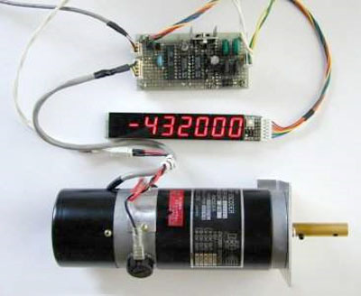
To capture the motor position, 52 kHz timer interrupt is used to sample the quadrature output from incremental rotary encoder and update current position register. Normally, a hardware buffer counter is used for the encoder interface to reduce load of the capturering process. However, SMC samples the input signals directly with only software process to reduce external components.
For more detail: DC Servomotor Controller System Meter using ATtiny2313 microcontroller
- What type of control does this closed loop servo mechanism support?
It supports real-time operations including position control, velocity control, and torque control. - How is the motor position captured in this system?
A 52 kHz timer interrupt samples the quadrature output from the incremental rotary encoder. - Does this project use a hardware buffer counter for the encoder interface?
No, it samples input signals directly using only a software process to reduce external components. - Can this system be implemented on other processors?
Yes, it is suitable for implementation on any embedded 32-bit RISC processors as middleware. - Is this project intended for practical use?
Yes, it can be used for practical applications with or without some modifications. - What signal does the system sample to update the current position register?
The system samples the quadrature output from the incremental rotary encoder. - What is the primary goal of using software processing instead of hardware buffers?
The goal is to reduce the number of external components required for the project. - Who created this experiment?
This experiment was conducted by Elm Chan.