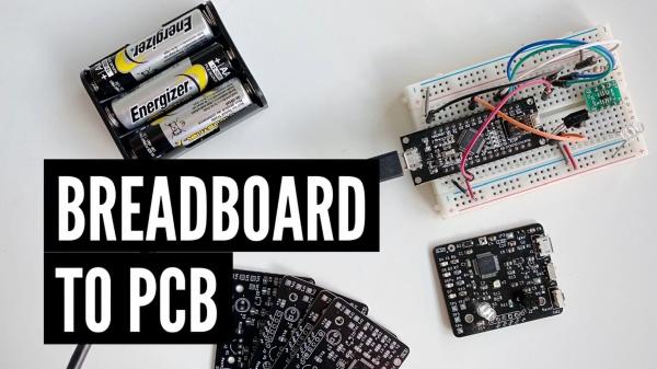
In Sayanee’s Basu’s video, we can look at the design considerations in the process of taking a breadboard prototype to a custom PCB, from the microcontroller to the various subsystems, to the power, the bootloader, and even how to deal with faulty components.

A breadboard can be useful for educational purposes, art projects, and even small testing. However, when we need multiple units or the components required are only available in SMD or other non-standard packages, a PCB is mandatory. Another advantage of a custom-made PCB is the capability of producing smaller and more robust units in higher quantities, which leads to a better project overall.
The first design consideration is the microcontroller. Developing a schematic can be intimidating at first, but when you look at some open-source designs for the same MCU and the datasheet, you will feel more comfortable. This is also the step where you choose the package and the variant of the microcontroller you will use, using the datasheet’s ordering information section for guidance. Lastly, you should make sure to check the availability and stock from the vendor before doing the layout.
After choosing your microcontroller, you should look at the subsystem level, dividing the breadboard prototype into the different sections. DrawIO can be used to draw some quick flowcharts and connect the subsystems. You can also divide subsystems into 3 different colors, according to their category: power, microcontroller and sensors/actuators. Every box in your subsystem can later become a logical block in your schematic, separating the major functional areas of your system. You can also use solder jumpers or zero-ohm resistors in order to separate the functionalities of these subsystems, which can be useful to test each individual subsystem individually.
Read more: DESIGN CONSIDERATIONS FOR TRANSFERRING A BREADBOARD PROTOTYPE TO CUSTOM PCB
