In this project we built a sketchpad based on LED matrix display with microcontroller and resistive touch screen control. We used a single point resistive touch screen to detect the user’s gesture and microcontroller’s analog/digital converter (ADC) ports collects the data and convert it to coordinates. We designed a LED drive circuit with shift registers and 3 to 8 decoders to make 4 8×8 LED matrix able to display the map we programed in the microcontroller. We calibrated the touch screen with LED matrix, and finally achieved that the matrix display the same gesture user draws on the touch screen. The sketchpad was built with Write/Erase/All Clear modes, which was shifted with 3 buttons. The LED matrix displays exactly what the user draw on touchpad instantly.
The main part of the device is four 8×8 led matrixes, which form a 16×16 big screen with 256 pixels, and a 4-wire resistive touch screen. The ATmega 1284p microcontroller get the coordinates from the touch screen and transfer the data to the LED matrix. We used two 74HC595 shift registers and two 74HC138 3to8 decoder to build the led power drive and makes the wires as simple as possible. Three buttons are built to set the sketchpad into write/erase/clear mode.
High Level Design
Rationale and Inspiration
We first browsed the previous projects on hackaday and came up with an idea that building a led sketchpad without actual touch on pad. To implement this, we did some research to figure out whether it was reasonable or not. First we tried to use infrared ( IR sensors and emitters) to determine the position of finger, then we tried to do the localization in ultrasonic way. However, after we talked with Pro. Bruce Land and did some experiment, we finally determined to use resistive touch screen to implement our idea, which was more reasonable in small scale with resolution about 0.5 cm or less.
Previous ECE4760 project group has used the resistive touchscreen (2012 Spring, TFT resistive touch screen , by Benjamin Harris and Philip Bernard). However, in our project, we have to divide the touch screen area into a 16*16 matrix which is corresponding to the dot matrix. Therefore, higher accuracy was needed and we did some modification based on the previous resistive touch screen code.
Logical Structure
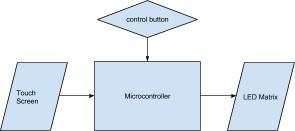
our device could be divided into four parts, as shown in the high-level block diagram.
Four internal 10 – bit ADC were used for calibrating the position touched on the resistive touchscreen. Two for X and Y position and two for the pressure calibration.
11 Ports were used to control two shift registers (74LH595) and two 3 to 8 decoder (HC138) which were used to drive the four 8*8 dot led matrix.
Timer0 Compare A interrupt for LCD display was used for testing.
Three buttons were used for user control.
Hardware Tradeoffs
First we decided to use the ports to drive the matrix directly, since the ports on 1284p have output high 5 Volts power, which was able to drive the leds without amplification. But it turned out the ports might not enough if we need to add other functions. Therefore, we decided to use shift registers (74LH595), which is also output high 5 Volts and could save a lot of ports.
In row direction, we used 3 to 8 decoders to scan each of line in high frequency so that it would looks like all the lines were lightened at the same time.
In this two ways we could use 11 ports total to drive the 16*16 matrix rather than 64 ports.
Software Tradeoffs
To improve the touch sensitivity of the touch screen, we modified the threshold of pressure value. Since when people were writing, it was actually lighter than press on a particular point on the screen. Therefore we adjust the threshold z that be determined as ‘valid’ touch to about 150 to 900 (see z calibration in software design).
Existing Products
There are lots of products related to led matrix.
Jeff Han, New York University “Muti-Touch Sensing through LED Matrix Design”, use LED themselves as photodiode sensor to determine the touch point on the matrix. .
We referred past ECE 4760 project,”TFT resistive touch screen” (2012 Spring) , by Benjamin Harris and Philip Bernard. We used similar concepts to calibrate the touched point on the touchscreen.
Our device differs from this product in execution and resolution. We implement the touch resolution to about 2.5mm.
Software Design
Top Logic:
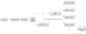
As top view, We’ll demonstrate our project into two parts, the main function, shows the top logic; the touchscreen part and the dot matrix driving part. The schematic are shown above.
Main Function
The main function mainly did four parts: 1,Initialization (Turn on the ADC since it is time consuming). 2, Determine the commands from user ( button pushed); 3, Call the touchscreen function and read the position to the led drive function; 4, Drive the led matrix.
ADC converter/Touchscreen
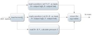
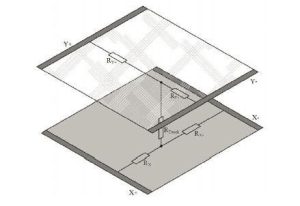
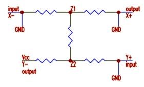
In this project, we use four internal 10 bit ADC converters (PINA0 – PINA3) to calibrate the position of the pressed point on the touch screen. For x position, we first set Y+ and Y- to input, set X+ to output high and set X- to output low, then read the ADC value which represents the x position. Then we could use similar methods to get the y position. Since we need a pressure threshold to determine whether we push the screen or not, we need to get the touch pressure as well.
Therefore the pressure would be calculated as:
Then we could get the (x,y, pressure) values.
16*16 dot Matrix Drive
In order to save the pins, we use two shift registers (74HC595) to implement serial input and parallel output. Since the 74HC595 output high as 5 volts drive power, we don’t need to use amplifier to drive the led matrix. Also, we use 3 to 8 decoder which is active low, to use three ports to control 8 pins of the led matrix. When we scan each of the row in a high frequency (16KHz per row, 1KHz refresh the whole matrix), then it looks like the whole matrix is lightened at the same time.
Time 0 Compare A Interrupt / LCD
We use LCD display to do the position calibration. We divided the screen into 16* 16 areas corresponding to the 16*16 leds. LCD was used to instantly display the values of x, y position and pressure.
Testing Method:
LCD Display for Touchscreen /Position Calibration
In order to get the instant value of the touched point on the touchscreen, we use the LCD to display the position values, but since the LCD updates in a low speed (200msec), it will significantly affect the display of the led matrix (1KHz), therefore the LCD display only used for testing.
As for the position calibration, since we just used part of the touch screen which equals to the area of four matrix. So first, we try to make sure that every led on the matrix could be lightened corresponding to chosen area on the touchscreen. Therefore, we had to determine the edge values of the touchscreen:
We define Xmin: 282; Xmax: 764; Ymin: 199; Ymax: 806. Since the area should be divided by 16*16, the x and y direction step was chosen as :
X step: (764-282)/16 = 30;
Y step: (806-199)/16 = 38;
Then we could convert the touch screen value into matrix position (0 to 15)as:
X: (TouchscreenX()- Xmin)/30 data type: integral
Y: (TouchscreenY()- Ymin)/38 data type: integral
LED Display Speed
We first tied no delay in the display cycle. When printed some patterns on the matrix, it turned out the display was flickering, therefore we tried some delays for each cycle. After we tried several values, 1ms per cycle turned out has the best results.
Dot Matrix Map
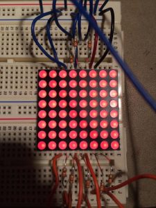
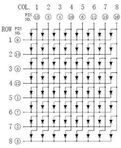
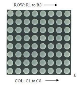
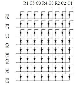
Every 8*8 dot matrix has 16 pins with 8 on the top and 8 on the bottom, which corresponding to the eight high pins and eight low pins with unknown order. So we test them manually as follows:
First, we connected all top 8 pins with pull up resistance to Vcc and all 8 bottom pins to ground. Then we found some of the rows and columns are not lightened. So we tried to pull up the wires pin by pin and see if changes the lighting results. In this method, we could first determine some of the pins controlled which rows or columns.
Second, change the connection of the pins which corresponding to those lines which are not lightened, repeat the first step and figure out the map.
Hardware Design
Our LED sketchpad includes a ATmega 1284p microcontroller, a 3.5” 4-wire resistive touch screen, 4 8×8 red led matrixes, 2 74HC595 shift registers and 2 74HC138 3 to 8 decoder led drive circuit, and a 12 V DC power supply.
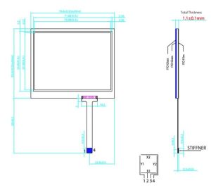
We ordered a resistive touch screen TS-TFT3.5Z by Newhaven Display International at Digi-Key.com. It is a 4 wire TFT resistive touch screen.
LED Matrix
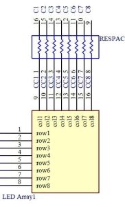
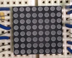
We used 4 red 8×8 small LED matrix display LEDM88SMR by Futurlec. Each matrix has 16 pins, 8 for columns and 8 for rows. Column pins are turned to high when leds in that column is on, and are turned to low when you want to turn off this column. Each column pin is connected with a 330 Ω resistor to protect the led from breakdown by large current.
From the wire schematics of the LED matrix, we got that it is impossible to turn on 2 and only 2 LED bulbs at different columns and different rows. To turn on 2 LEDs at different columns and different rows, we need to set 2 columns high and 2 rows low. However the result is there will be at least 4 leds being turned on, which is not the display we want. Consequently with a static display, it is impossible to display the arbitrary patterns we design and is not able to achieve the sketchpad function we desired.
We figured out that only turn on 1 row of LEDs each time and scan the matrix row by row at a very high frequency of 62.5 Hz (1ms delay at per row) can achieve a progressive scan display, so that we can display an arbitrary pattern on the matrix. More details are discussed in the software design part.
3-8 Line Decoder
Since we got 4 matrix with 16×4 = 64 pins to wire up, we are unable to connect all the pins to one microcontroller. In our design, we put the pins controlling the same row in parallel which downsizing the 32 pins into 16 rows. Then we connected the 16 rows to 2 3-8 line decoder.
The decoder we used is SN74HC138 by Texas Instruments. It operates at 2-6V and has 4mA output drive at 5V. There are 16 pins for each decoder. Vcc is connected to high while GND, G2A, G2B is linked to ground. Pin A, B, C and G1 is controlled by the microcontroller. Pin Y0-7 is connected with 8 rows of the LED matrix. According to the function table, proper state of pin A, B, C, G1 can set one of Y0-7 pin low or all at high.
Thanks to that function, we can use two 3-8 decoders (or one 4-16 decoder) to set one of the 16 rows of the matrix low that is to choose this matrix to turn on, or set all the rows high that is to turn off the whole matrix. Particularly, in our final work, pin A, B, C, G1 of 1st decoder is connected to PORTD 3-6 at MCU, and pin A, B, C, G1 of 2nd decoder is connected with PORTB 3-6.
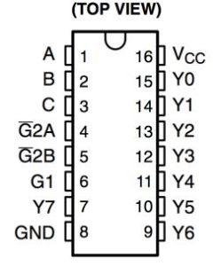
The result is we could control the 16 rows, 32 pins from LED matrix by only 4×2=8 pins on the microcontroller.
8-bit shift register
As the LED matrix operates at a progressive scan mode, LED bulbs from different columns need to be turned on when one row is on. 3-8 decoder is not appropriate here as it only has 9 states which is not enough for the column display.
We chose 2 SN74HC595 8-bit shift registers from Texas Instrument to achieve the different column display while reducing pin numbers. SN74HC595 operates at 2-6V and has 6mA output drive at 5V.
SRCLR is always linked to high that we close the clear function. OE is always low that the outputs are always enabled. Pin SER, SRCLK, RCLK of 1st shift register is connected to PORTD 0-2 and pin SRCLK, RCLK are connected with pin SRCLK, RCLK of the 2nd shift register that the two register share a clock control. Pin QH’ is at 1st register is connected to pin SER at 2nd register that the same signal is shifted to the 1st one first and then goes to the 2nd one. Pin QA-H is linked to the column control pins of the LED matrix.
As a result, only 3 pins of microcontroller were used to control all 16 columns of the whole matrix. Details will be discussed in the software design part.
Buttons
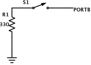
3 buttons are connected to PORTB 1, 2, 7 is set as output and is pulled high. When button is pushed the port will be connected to ground and PORTB will read low. We use this function to toggle the state between Write/Erase/Clear.
Results
Speed of Execution
The most time consuming part in our programme is the led matrix driving part. The time for driving the whole matrix need 1 ms. Which means the refresh frequency for the whole matrix is 1 KHz (16KHz scanning each line). It was very slow comparing to the resistive touch screen speed, which was 200us each for x, y and z valued detected.
Accuracy
Since the 10- bit ADC’s resolution is very high, and we need to convert the touchscreen value to the matrix position, which was (0,15) for x and y position. Therefore, the accuracy was mainly depend on the area of touch screen and led matrix. The size of valid touchscreen area was exactly the same with the sum area of four led matrix, which was a 40mm by 40mm square. We divided the area into 16 by 16, which is corresponding to the 16 by 16 led matrix. Therefore, the resolution of the touch screen detection is:
40mm/16 = 2.5mm
As for the led matrix display, the size of a led dot is 1.9 mm (diameter), which determined the display resolution.
User Evaluation
We test our device on a variety of users drawing different patterns on our sketch pad. It turned out that the touch screen is sensitive enough to accomplish a quick response and high resolution. We found that most of the users could write distinguishable words on the led matrix through touchscreen and the lighting intensity is good enough as well. Since we added write/ erase/reset buttons for user control, the sketchpad is fairly easy for users to write and erase while keeping a desirable accuracy.
Safety
Our device is quite safe because we don’t need users to directly touch the lighting parts. All the parts we used in our project is small voltage.
Interference with other people’s design
The only part is similar with our people’s design is the resistive touch screen part. But we did modification and improve the resolution.
Usability
Led matrix has a pretty good lighting conditions with high intensity and comparatively low energy consumption. And for our device, we combine the resistive touch screen with the drive of led matrix with was very easy for users to write, erase and read.
Conclusions
Future work
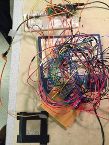
With additional time, we will try to use muti- colored led matrix to do the displaying. Then not only words could be write on the sketch pad, we could even also draw pictures with colors on the matrix. Also, since we first try to build the touch screen right above the four matrix and because there were too many wires and we finally didn’t accomplish that. So further improvement might be done if we could build up PCBs for the hardware part.
Standards
IEEE safety standards for consumer products outline the need for a “better user interface”. [ISO 9241-920:2009, “Ergonomics of human-system interaction — Part 920: Guidance on tactile and haptic interactions”] . To accomplish that, we integrated different user commands for user to easily control: external buttons separately for write erase and reset. Our device is very easy to implement user- device interaction, since user is easy to see what is written by the instant displayed messages.
Intellectual Property Considerations
Except for the touchscreen and UART part, the code is solely written by us. The touthscreen part was written by Benjamin Harris and Philip Bernard. The UART code was provided by Pro. Bruce Land through course ECE4760.
Ethical Considerations
During the design of our project,we adhered to the IEEE Code of Ethics. We made design choices to ensure safety for the public and for ourselves while developing a quality product. While constructing our device, we constantly checked for short circuits, corrupt components, and made sure all electrical components were properly insulated. To our project inspiration and referenced works,we gave proper acknowledgement. We assisted our colleagues in their design processes, supporting them with constructive criticism. Most importantly, we were honest with all steps of our development process, recognizing and correcting errors when appropriate. As for safety, we maintain a safe and controlled environment when testing our device on a variety of users. Since our build of led matrix need lots of wires, we keep checking the connections of power and ground to avoid short circuits and keep the workstation we used in an appropriate order.
Legal Considerations
To our knowledge, our device does not violate any legal regulations.
Source: LED Sketchpad

