Summary of Digital Clock Using Microcontroller (AT89S52 Without RTC Circuit)
Clock is a device that counts and shows time. This project builds a digital clock with alarm using an AT89S52 (8051) microcontroller, three 7-segment displays, LEDs for AM and alarm indicators, a piezo buzzer, crystal oscillator, capacitors, resistors, and push switches. The 12 MHz crystal and 8051 timer interrupt produce accurate one-second ticks; display digits are driven via port pins (non-multiplexed). Alarm is set via buttons (hour, minute, save) and can be toggled off by double press; buzzer emits frequency-coded tone at alarm. Code built in Keil generates the hex file.
Parts used in the CLOCK with ALARM:
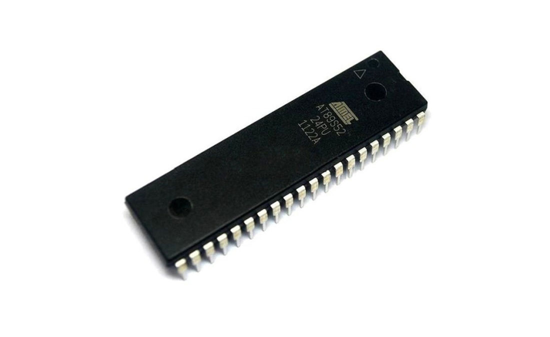
- Microcontroller AT89S52 (8051 family)
- Three 7-segment displays
- Crystal oscillator 12 MHz
- Capacitors (10uF, 33pF or 22pF)
- LEDs (AM indicator, alarm indicator, seconds indicators)
- Resistors (330 Ohm)
- Buzzer (piezo)
- Push switches (hour, minute, save, alarm)
- Soldering iron, wires, flux, power supply (not included)
Lets describe a clock… “Clock is a device that counts and shows time(relative)”!!!
Guess I said it right so lets make a CLOCK with ALARM feature.
NOTE: it will take 2-3 minutes in reading please read the whole project or else I will not be responsible for any part damage.
Step 1: COMPONENTS REQUIRED
6 components needed :
1. Microcontroller (I have used AT89S52-8051 family), any programmable microcontroller can be used.
2.7 segment display
3.Crystal oscillator (12MHz)
4.Capacitor (10uF, 33pF/22pF)
5.LEDs
6.resistances (330 Ohm)
7.buzzer (piezo)
8.push switches
And I’m not including soldering iron, wire, flux….. electricity !!! help me out 🙂
Step 2: Circuit Diagram
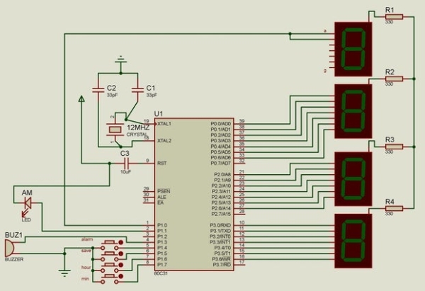
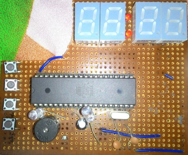
This is the circuit diagram of the digital clock using 8051 microcontroller.
As we can see the microcontroller is connected to three 7 segment display with distinct ports not multiplexed and the last hour digit is only connected to a pin as it only shows 1.
LED and buzzer are self explanatory according to the code.
1 of the LED is for AM and I have connected another LED not shown in the figure for alarm.
Crystal Oscillator of 12MHz is connected to clock speed and attaining the exact 1second counting using the interrupt property of the microcontroller.
THE MIDDLE LEDS DENOTING SECOND ARE CONNECTED TO “28TH AND 32ND” PIN.
Please pardon me, 3 LEDs aren’t shown in the circuit diagram for my laziness.
28th pin LED: first 30 second blink
32nd pin LED: rest 30 second blink
****contributing to a whole minute!!*** i’m sure after this project I came to know 60 second makes a minute!!! WOW
Step 3: Coding
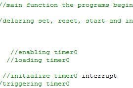
I have used keil software to built a C code for the RTC using microcontroller and getting hex file.
REFER TO CODING PORTION ON THIS TO KNOW MORE!!
The fundamental thing in the coding part is, when the pin of each port will toggle for showing the digit related to each 7segment display.
The interrupt property of 8051 is used to count and reload per second. for example only, Just like creating a delay function with argument 1 causing 1second delay. (TMOD,TL0,TH0,IE every value contributes to the time making)
The LED for AM is programmed for alternate 12 hour.
As well as alarm can also be set for AM or PM specifically and the buzzer pin is passed with frequency code to buzz on the alarm time. Alarm button with min, hour & save switch is used for setting alarm. On twice clicking alarm disables alarm feature.
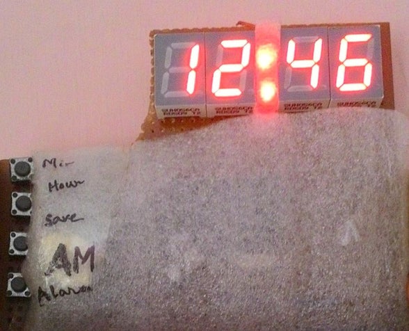
Step 4: Finally…
ALL done !!! Now iT’S time to enjoy the clock that’s bright and exact.
NO DISCREPANCIES WITH REAL TIME…
IF you liked it “make it” and “make it your favorite”…
Source: Digital Clock Using Microcontroller (AT89S52 Without RTC Circuit)
- What microcontroller is used in the project?
The project uses an AT89S52 microcontroller from the 8051 family. - How is accurate one-second timing achieved?
Accurate one-second timing is achieved using a 12 MHz crystal oscillator and the 8051 timer interrupt (TMOD, TL0, TH0, IE configuration). - Are the 7-segment displays multiplexed?
No, the three 7-segment displays are connected to distinct ports and are not multiplexed. - How is the AM indicator implemented?
An LED is programmed to indicate AM by toggling for alternate 12-hour periods. - How is the alarm set and saved?
The alarm is set using push buttons for minute, hour, and a save switch, and can be disabled by clicking the alarm button twice. - What component produces the alarm sound?
A piezo buzzer is used, and the buzzer pin is driven with frequency code to generate the alarm tone. - Which pins are used for the seconds LEDs?
The seconds LEDs are connected to the 28th and 32nd pins, blinking for the first and rest 30 seconds respectively. - What software is used to build the code?
Keil software is used to build the C code and produce the hex file for the microcontroller.