Summary of Digital Soil Moisture Meter
This article describes a digital soil moisture meter designed for irrigation farms. It uses two metallic probes to measure soil resistance, converting it into an electrical value processed by an Arduino Nano V3 microcontroller. The system features a 16×2 LCD display to show moisture levels and includes calibration via preset VR1. It operates on a 5V DC supply or external 7–12V power.
Parts used in the Digital Soil Moisture Meter:
- Metallic probes (sensor head)
- Arduino Nano V3 platform
- 16×2 LCD panel
- Regulated 5V DC supply (or 7V–12V external DC)
- 10-kilo-ohm preset (VR2)
- 100-ohm resistor (R2)
- 10-kilo-ohm preset (VR1)
- Backlight lamp
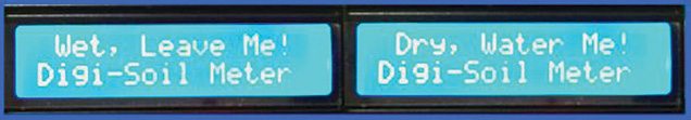
A digital soil moisture meter is used for indicating the water content of a given soil sample. As crop production requires water at different stages and in different amounts, it is important to measure soil moisture from time to time to know its status.
The digital soil moisture meter circuit presented here, for monitoring the soil moisture content in irrigation farms, is an electronic device that measures soil moisture content accurately and precisely. It measures the resistance of flow of the electric current between two metallic probes. These probes act as sensor elements that register moisture and change it into an electric value. This value is further processed into information in the form of an electronic display.
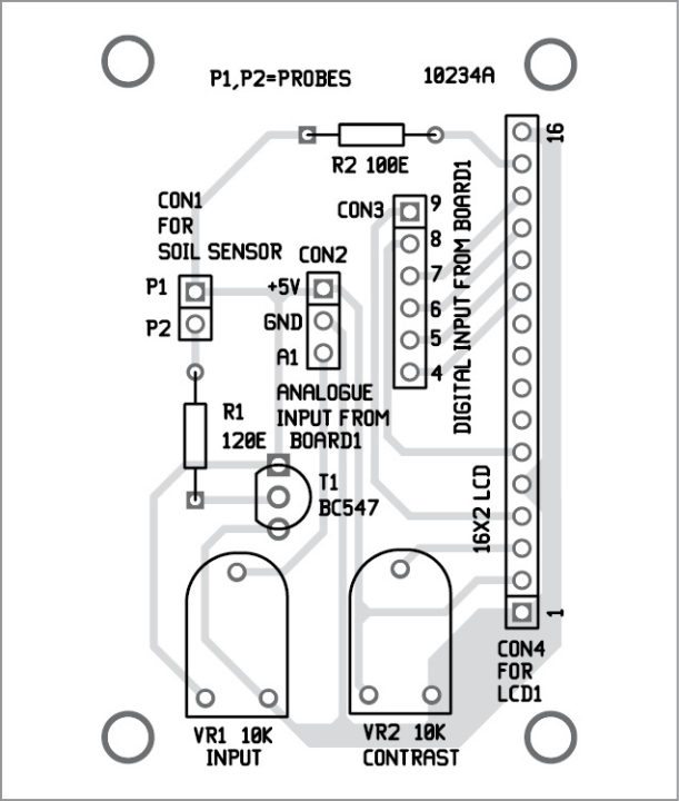
Digital soil moisture meter circuit
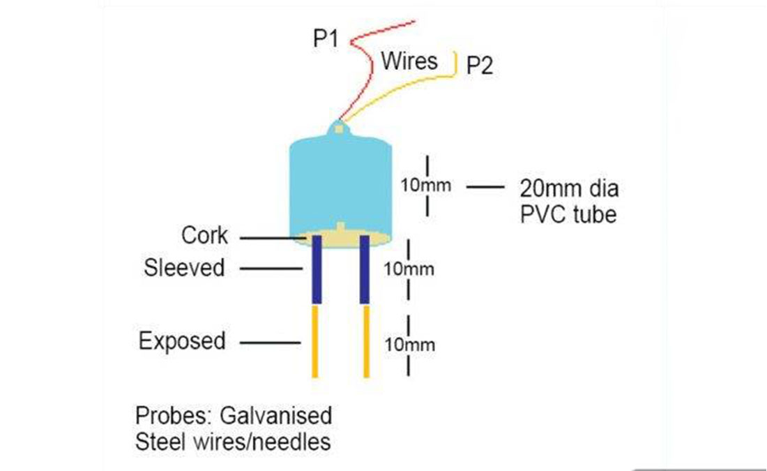
Front-end of the digital soil moisture meter is a simple soil moisture sensor head, built around a few easily-available parts. Working of the sensor head electronics is self-explanatory, so just follow the conceptual drawing (and schematic drawing) shown in Fig. 1 to proceed with its construction.
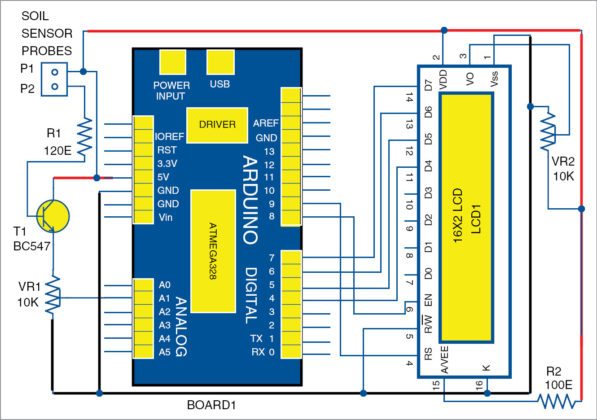
Complete circuit diagram of the soil moisture meter is shown in Fig. 2. After construction of the sensor head, power it off a regulated 5V DC supply.
Insert the probes of the sensor head into the soil to determine its moisture content, and carefully adjust the preset VR1 so that voltage just above 3V is available at pin A1 of Arduino (Board1) if the soil is wet enough.
Construction and testing
Repeat the calibration process with randomly-collected soil samples ranging from very dry to very wet, depicting different moisture levels. Re-tune VR1, if necessary, until you are satisfied with the calibration process. (Note that the depths of penetration of the probes into the soil affect calibration.) Link the sensor head to the rest of the hardware to complete the project.
Rest of the hardware is a combination of Arduino microcontroller and a solid-state display panel. For compactness, Arduino Nano V3 platform is used to drive the 16×2 LCD panel.
Though a 6V battery pack is used to energise the hardware setup, you can also use external DC power in 7V – 12V range at VIN of Board1 without any problem. The 10-kilo-ohm preset (VR2) is included to adjust the contrast level of the display. Similarly, the 100-ohm resistor (R2) limits the operating current of the backlight lamp inside the display panel.
For more detail: Digital Soil Moisture Meter
- How does the sensor measure soil moisture?
It measures the resistance of electric current flow between two metallic probes. - What is the purpose of preset VR1?
It is adjusted to set the voltage above 3V at pin A1 when the soil is wet enough. - Can I use an external power source instead of a battery?
Yes, you can use external DC power in the 7V to 12V range at VIN. - What microcontroller drives the display?
An Arduino Nano V3 platform is used to drive the 16×2 LCD panel. - Why is resistor R2 included in the circuit?
The 100-ohm resistor limits the operating current of the backlight lamp inside the display panel. - How do I adjust the display contrast?
You use the 10-kilo-ohm preset VR2 to adjust the contrast level of the display. - Does probe depth affect calibration?
Yes, the depths of penetration of the probes into the soil affect calibration. - What voltage should be available at pin A1 during calibration?
The voltage should be just above 3V when the soil is wet enough.