A while back, I added a fan controller to my Topward 6603A power supply. Later on, when I bought a used programmable power supply (PPS-2322) I had to do the same thing. Both of those builds were done on protoboards but I had a feeling that many of my other projects could use a similarly designed fan controller as well. So I thought why not just have the PCB professionally made?
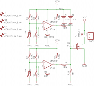
The schematics I designed for this dual sensor fan controller is shown below (the Eagle file can be downloaded towards the end), it is largely based on the same as the designs I used previously.
To make the design more useful, one channel is marked as optional (see components with * on the silkscreen) so that you can build either a single sensor fan controller or a dual sensor one. With two sensors, the control signal is or’d with both of the sensor input and if either side of the temperature exceeds a predefined threshold the fan will be turned on. This is useful in situations where power devices from multiple channels share the same heat sink (see my previous explanation).
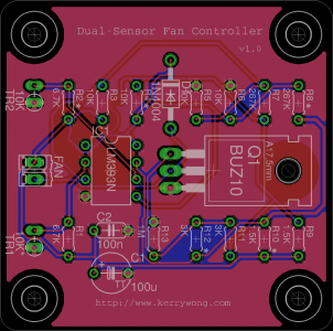
For the PCB service, I used Seeed Studio’s Fusion PCB. I was pretty happy with the board result when I made my Arduino compatible board using their service. It took just over three weeks for the boards to arrive. As you can see from the pictures below, the quality is pretty good. A couple of traces were not perfect (the thin trace from the comparator pin 4), but that was due to my design not a result of the manufacturing process. I also forgot to include a power header. Thankfully, the electrolytic capacitor footprint can be used as the power input. Despite these minor imperfections, the boards are perfectly useful. But if you are going to use this design to make your own board you might want to add a two pin header for the power coming in.
For more detail: A dual sensor fan controller build


