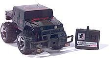
Summary of EE476 – Final Project Hummer RC Truck
### Summary This project enhances a Hummer RC truck by replacing its original circuitry with an Atmel microcontroller system. The team implemented wireless communication using a Ming Microsystems transmitter-receiver pair to control steering and speed. To improve handling, they substituted the car's inefficient electromagnet steering with a mini ball bearing FMA servo for precise angle control. Additionally, they tested two methods for variable DC motor speed: Pulse Width Modulation (PWM) and current limiting via a digital-to-analog converter.
Parts used in the Hummer RC Truck:
- Atmel microcontroller
- Ming Microsystems receiver transmitter pair
- DC motor
- Digital-to-analog converter
- Mini ball bearing FMA servo
- Power transistors
Introduction:
For our final project, we decided to enhance the controls of a Hummer RC truck. Our main objective was to demonstrate that an Atmel microcontroller together with basic hardware building blocks can replace all of the car’s original circuitry. Improving the RC truck’s handling involved adding analog control over steering and speed. The original construction of the car hindered this idea and forced us to resort to some mechanical engineering (mounting a servo) to resolve the problem! Overall, the project was a great deal of fun and involved a lot of tinkering with hardware (including dangerous flirtations with nearly exploding power transistors!)
High Level Design:
In order to emulate the functionality of the original RC car, we had to use 2 microcontrollers; one at the transmitter end to process user input and transmit data and one at the receiver end to pick up that data and control the car’s motors. We found a cheap but reliable way of establishing wireless communication between the two microcontrollers in the form of a receiver transmitter pair by Ming Microsystems.
We wanted to run the dc motor at the rear at variable speeds. Two options were available to us: One is to switch it on and off so fast that it appears to be running at an intermediate speed. By modulating the width of the pulse to the switch we could achieve various duty cycles. The other approach is to limit the current to the motor so as to slow it down. This requires an analog input to the motor and therefore a digital-to-analog converter. We ended up trying both ways and our results are documented below.
The car’s front wheels were originally driven by a magnet. By flipping its polarity, the wheels are repelled all the way to the left or right. This didn’t suit our needs. The other disadvantage of the electromagnet is that it constantly draws current from the battery (~400 mA). By using a servo, power consumption is significant only during transitions of the servo arm. The mini ball bearing FMA servo we used allowed us to have three different steering angles. More steering angles were not conceivable because of the design of the axial for the front wheels of the car.
For more detail: EE476 – Final Project Hummer RC Truck
- What was the main objective of the project?
The objective was to demonstrate that an Atmel microcontroller and basic hardware can replace the car's original circuitry while improving handling. - How did the team establish wireless communication between the microcontrollers?
They used a cheap but reliable receiver transmitter pair by Ming Microsystems. - What are the two options available for running the DC motor at variable speeds?
The options are switching the motor on and off rapidly using pulse modulation or limiting the current to the motor. - Why was the original electromagnet steering mechanism replaced?
The electromagnet constantly drew ~400 mA from the battery and could only flip polarity rather than offer analog control. - What specific servo was used for the steering mechanism?
A mini ball bearing FMA servo was used to allow three different steering angles. - Does the servo consume significant power during operation?
No, power consumption is significant only during the transitions of the servo arm. - Why were more than three steering angles not possible with the servo?
The design of the axial for the front wheels limited the number of conceivable steering angles. - What type of input does the current limiting approach require for the motor?
This approach requires an analog input to the motor, necessitating a digital-to-analog converter.