Kang Li(kl694) and Zhenxuan Qiu(zq39)
For our ECE 4760 final projec, we built a pair of toy “cat ears” using electroencephalography (EEG) with the AVR microcontroller. The basic function of it is that it can change the gesture of the “Ears” based on the participant’s emotion. The user doesn’t need to do anything except for thinking.
Introduction
Magic Cat Ears is a next generation toy. It reads user’s excitement degree and controls the ears to show different gestures. To make it work, one just need to put it on the head and connect the system properly. It will then do all the work automatically.
The design is built with Atmel microcontroller ATmega 1284P, a pair of EEG electrodes, step motors and a series of analog signal processing circuits.
We use EEG technique to capture how relax or exciting the user is. EEG (electroencephalogram) is able to show a wide range of electromagnetic radiation from human brain. Here we only capture α wave to find out what we want. Basically, the magnitude of α wave goes down when people is exciting, and goes up when people is relaxing. So the excitement detection with α wave is possible. However, the key point, which makes it hard to implement the technique, are the noise and the narrow bandwidth of α wave. Since α wave is only a part of electromagnetic radiation from our brain, there will much interference from other waves. Also, electromagnetic radiation from the working environment will count as noise. The bandwidth of α wave is only 4 to 5 Hz, which makes it very hard to distinguish.
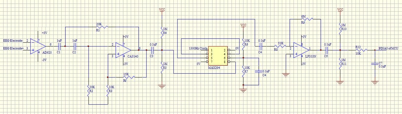
The EEG sensor we build is composed of two amplifiers, a high-pass filter, and a low-pass filter. The key components to solve the above problem are the filters. The second order high-pass filter alleviates the interference from θ wave, δ wave and other low frequency noise. The eighth order low-pass filter bans the interference from β wave and high frequency noise. Two amplifiers ensure that the output of the signal processing circuits large enough so the ADC of the microcontroller can recognize with relatively quantization error.
To show the level of excitement, several gestures are set according to the signal from the sensor system. Some random gestures will fulfill the time when the status of the user is relatively stable so you never feel the device is dead.
Nowadays, EEG is not only attracting attention from the medical device manufactures. It is also highly valued in other fields like psychology study, smart control. Our device is an example to show how it could be combined with toys and our daily life. And in the future, when the technique becomes mature enough, more interesting devices will be built with it for sure.
High-Level Design
Inspiration of the project
We got the idea from the toy “Necomimi” designed by NeuroSky company. http://www.necomimi.com/ . We like this idea very much. So we want to build one of our own
Schematic of the logic of the project
Hardware Design
The MCU chip we use to develop this project is ATmega 1284P. And we have five basic parts of the analog signal processing board: the amplifier circuit, the low-pass filter circuit, the high-pass filter circuit, another amplifier circuit after low-pass filter, and the motor control circuit.
For the electrodes, we select premium reusable silver patch electrodes. We use two electrodes in our design. The positive electrode is connected to the forehead of the user and the negative electrode is connected to one of the ears.
For the safety concern, we only use AA batteries to provide power to ATmega 1284P and the analog signal processing board.
1. Analog signal processing board
The AD620 amplifier circuit
We use AD620 as our main amplifier chip. The reason for selecting AD620 is that it has very high input impedance, which is required for EEG detecting. We connect the PIN1 and PIN8 of AD620 with a 1 k ohms resister to get the gain of around 50. The gain of AD620 can be calculated by the fomula
The high-pass filter circuit
We use CA3140 to build our second order high pass filter. CA3140 is integrated circuit operational amplifier with Very High Input Impedance.
Because the resistor and capacitor values are the same, the cut-off frequency

And the gain
![]()
The low-pass filter circuit
We use MAX294 as the chip of our low-pass filter circuit. MAX294 is an 8-order low pass elliptic filter, with the corner frequency of 13Hz in our design. The clock to corner frequency ratio is 100:1, which means the external clock we are using is 1300Hz. The external clock generated by the MCU is connected to the PIN 1 of MAX294.
Because the range of the input of the MAX294 is 1~4V, we have to add DC offset as shown in the circuit diagram.
Parts List:
|
Name
|
Digikey Part Number
|
Quantity
|
Cost(USD)
|
|
AD620
|
AD620ANZ-ND
|
1
|
7.94
|
|
CA3140
|
CA3140EZ-ND
|
1
|
1.89
|
|
MAX294
|
MAX294CPA+-ND
|
1
|
10.21
|
|
LF353N
|
LF353NFS-ND
|
1
|
0.55
|
|
Mega1284
|
1
|
5
|
|
|
Custom PC board
|
1
|
4
|
|
|
DIP socket
|
4
|
0.5*4=2
|
|
|
Resistors and capacitors
|
0
|
||
|
Small solder board (2 inch)
|
1
|
1
|
|
|
Audio cable
|
1
|
2.78
|
|
|
DC 5V Stepper Step Motor + Driver Test Module Board ULN2003
|
2
|
2.5*2=5
|
|
|
Premium Silver Tens Electrodes Pads 4 Square Highly Adheresive Tens Pads
|
1
|
5.08
|
|
|
Hat
|
1
|
3
|
|
|
AA batteries
|
10
|
13.99
|
|
|
total
|
60.44
|
For more detail: EEG Magic Cat Ears Using Atmega1284