Do you face such situations when you leave your reading lights, table fans or soldering irons without switching them off and later realize that they were on for too many hours which subsequently jumps off your electricity bills? Well, if you have such a problem of forgetting things which probably most of you would have (including me :P), you have just found the right thing! This project will detect your presence on your work chair and then switch on and off appliances connected to it accordingly.
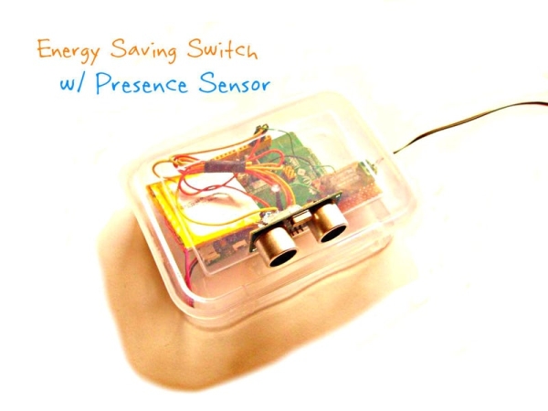
The project uses an ultrasonic sensor connected to the Mediatek Linkit ONE as it’s brain. By detecting the distance from the sensor to your chair, it can detect your presence as the distance will decrease when you are sitting on the chair. The relay connected to linkit one gets activated when you are sitting on your chair thus switching on the appliance while it switches it off as you leave. Thus, this project will greatly help to reduce your electricity bills as any appliance from soldering irons and hot glue guns to lights and fans can be controlled using this appliance.
The project is not very complicated and easy to make thus can be a good way to start with linkit one. There are innumerable number of modifications you can make to this project. Remember to post a feedback in the comment section below. Do post the pictures of your own project if you’ve made one yourself. Don’t forget to follow for more great projects!
For more cool projects, videos and facts, like my new facebook page – Frozen Solenoid
Step 1: Parts and Tools
The following parts and tools are required to make this project. The total cost was around $70 or 4200INR. If you already have a linkit one or got it from the giveaway recently, the total cost will be reduced to $10. No complex are required so you can buy all of them online.
PARTS:
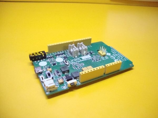
• 1x Linkit ONE
• 1x Lithium battery for powering the board
• 1x Ultrasonic sensor
• 1x 3v or 5v Relay
• 1x BC547 transistor
• 1x 1K resistor
• 1x Screw terminal
• 1x 5v USB adapter
• 4x Male to female jumper wires
• A suitable enclosure for your project
• Perfboard
• Rainbow wire
TOOLS:
• Soldering iron
• Soldering wire
• Hot glue gun w/glue sticks
• Wire cutter/stripper
• Pliers
• Drill
Step 2: Connect the Ultrasonic Sensor
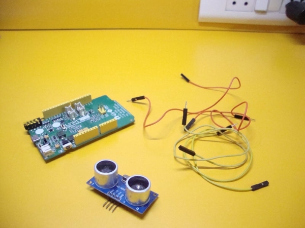
The very first step in the building process is to connect the ultrasonic sensor to the linkit one board. The sensor here serves the main purpose of the project, that is calculating the distance. As most of you would already know, my transmitting ultrasonic waves and then receiving the reflected ones, an ultrasonic sensor is able to calculate the distance of the obstacle present in front of it.
Here, this sensor will be used to detect your presence. There is no kind of a human sensor present which will be used but your presence can be detected by using simple logic. When the sensor will be kept at your workbench facing your chair, the distance would be more when you are not sitting on your chair while it would be comparatively less when you are sitting. So when the distance becomes less that the set threshold, the board processes the signal of the sensor and activates the relay which switches on your appliance. Understanding all this would be easy until you make it difficult yourself as there rocket science involved in this project.
Connect the sensor to linkit one using some male to female jumper wires according to the following:
1. Vcc —- Linkit one’s 5v
2. Gnd —- Gnd
3. Trigger —- D2
4. Echo —- D3
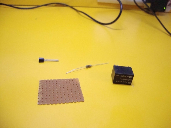
Step 3: Make the Relay Board and Connect It
The aim of the project as told earlier was to switch on an appliance during your presence. Now to give power to something, you can’t just take the output from one of the digital pins on linkit one as their output current is too less to power something. So the trick used here is to power a relay from the digital pin (a relay is a magnetic switch which on receiving a weak signal, closes it or switches it on). So, when the sensor detects your presence, the digital pin gives a weak signal to the relay which then switches on the appliance it is connected to.
The output current of linkit one is not enough even to power a relay you there is a need to use an external transistor. Since we want our appliance to be switched on when the output is high, we would be using Pole and NO pins of the relay. On receiving a high output, these two pins get connected thus closing the switch.
An important thing to consider while using a relay is the voltage and the current ratings. Voltage rating is the minimum voltage that is required to activate it while current rating is the maximum current that the Pole, NC and NO pins can handle. Here I have used 3V, 3A relay. You can also use a 5V relay but higher than that would not work. Power rating should not be less that 2A. It should be more that 5A if you want to power any AC appliance.
For connecting the relay, first you need to solder everything to a piece of perfboard and then connect it to linkit one. Refer to the schematic for the same. You need to solder a screw terminal to connect the wires which will then be connected to your appliance.
Step 4: Upload the Code
Upload the code given in the ino file given below to your linkit one. Make sure that the on-board switches 1,2 and 3 should be in UART, USB and SPI positions respectively before uploading the code.
If you have never uploaded a code to your linkit one, you can follow my Linkit ONE Getting Started Guide for setting up your board for the first time.
Note:
1): You need to download the NewPing library before compiling the code else it will show a compilation error.
2): Change the threshold distance according to your requirement. First calculate the distance between your chair and the place where you will keep the device in cms. Then set the threshold at a little less distance than your calculated one.
#include
int threshold_dist = 50; // Change the threshold distance according to your requirement
NewPing sonar(2, 3, 400);
void setup()
{
Serial.begin(9600);
Serial.println(“Ready!”);
pinMode(4, OUTPUT);
digitalWrite(4, LOW);
}
void loop()
{
unsigned int uS = sonar.ping() / US_ROUNDTRIP_CM;
Serial.print(“Distance: “);
Serial.print(uS);
Serial.print(“cm”);
Serial.println();
if(uS >= threshold_dist)
{
digitalWrite(4, LOW)
Serial.println(“Current State: OFF”);
}
if(uS < threshold_dist)
{
digitalWrite(4, HIGH);
Serial.println(“Current State: ON”);
}
delay(500);
}
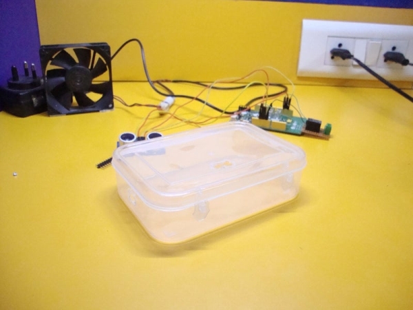
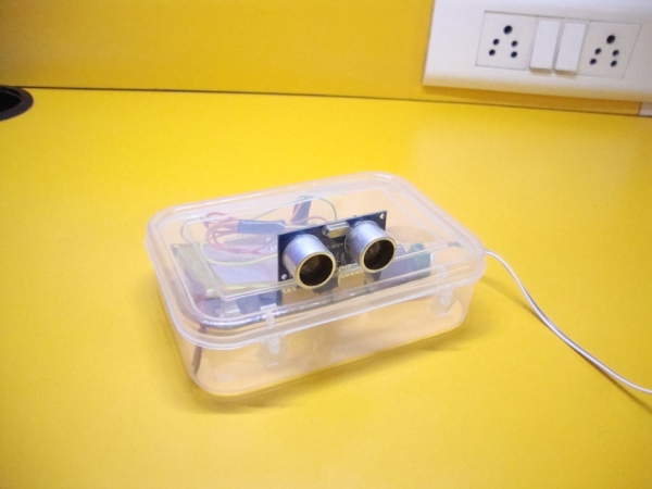
Step 5: Connect the Battery and Mount Everything Inside an Enclosure
After uploading the code, connect the lithium battery provided with the board to the female socket present at the bottom left corner of the board. Slide the switch to BAT position and you should see the on-board LEDs light up.
Now hot glue everything inside a proper enclosure. The best option can be to use a plastic drug case which is very easy to work with but there are a variety of other options you can use as well. Make sure that the ultrasonic sensor should be vertically facing towards you when the box is kept still. Hot glue the sensor to a height so that it can easily detect your presence.
Lastly, protect all the wires with some insulating tape.
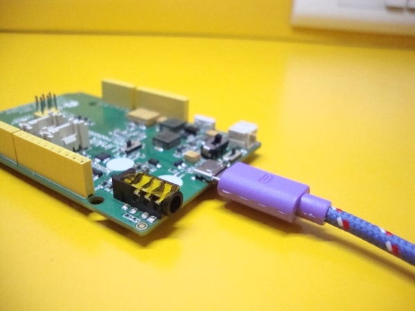
Step 6: Connecting to an External Power Supply for Long Use (Optional)
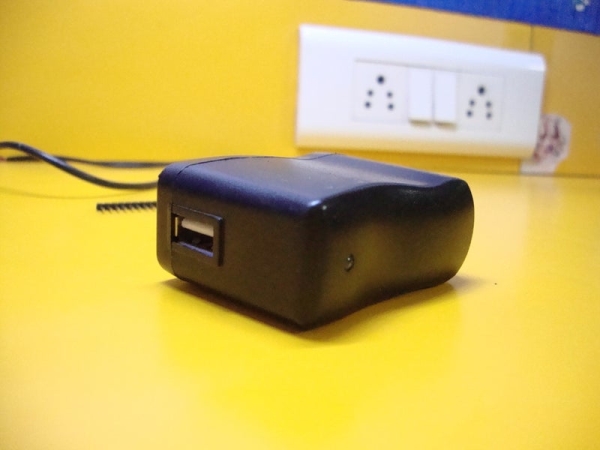
If you want to use this device for a long period of time, unfortunately the battery wouldn’t last for more than 2 or 3 hours. The solution to this problem is to use a simple USB charger or a wall wart for uninterrupted power supply.
For this, first disconnect the battery from your linkit one. Then connect a USB charger to it using a micro USB cable. Slide the switch to USB position and you should see the on-board LEDs light up.
Step 7: How to Connect to an Appliance?
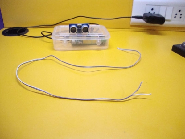
Now you’re all done with the building process of the project. The last step left is to connect this project to the appliance you want. As told already, the relay will act as a switch and will close it on detecting your presence. So to connect an appliance to this device, you just have to do the same that you do to connect something with a switch. Instead of connecting two wires to a switch, you have to connect those wires to the relay pins (NO, Pole).
First take two long pieces of wires and connect them to the screw terminals that you soldered earlier. The wires should come out of the enclosure. Now you can’t just connect these wires to any appliance. You have to consider a few things before connecting something.
Firstly, you should consider the current rating of your relay. Powering small DC appliances should not be a problem but when it comes to AC appliances, you should be cautious. Ofcourse you cannot power big appliances like air conditioner and room heaters (the rating should be more than 15A). For small ones like table fans, desktop lamps, 3-5A relay can be used while you can power only DC appliances with any relay with current rating less than 2A (you can still power big ones but with the risk of burning the relay terminals). You should also check whether the terminals can handle AC current or not. It is always better and safe to use higher power relays. The voltage rating should also be more than what is supplied in your house.
The image above shows the device first connected to an LED, then a 12V CPU fan and finally a 10W AC bulb. You can follow the schematic given above for making the connections.
Step 8: You’re Done!
So you’re finally done with one more linkit one project! Your electricity bills would now be reduced to a certain extent now! But that’s not the end. You can try an experiment with different threshold distances or extend the project by adding more features to it. One of the ideas can be to use a higher power relay to power big appliances. You can even experiment with different sensors.
This brings another instructable to an end. Hope you liked it. Remember to leave a feedback below. You can also post your own ideas, modifications or mistakes in this project in the comment section below. I would really appreciate it. If you think that this project was good, you can vote for me in the only contest this instructable is entered in.
Don’t forget to follow for more great projects!
For more cool projects, videos and facts, like my new facebook page – Frozen Solenoid
Thanks for watching 🙂
Source: Energy Saving Switch With Presence Sensor