Summary of EPROM Display using ULN2308A microcontroller
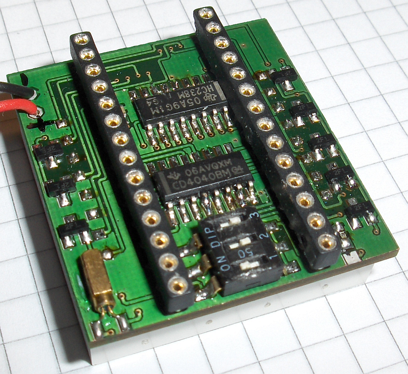
The project involves creating an animated 8×8 LED matrix display using old 27C256 EPROMs. Each EPROM stores 4096 frames, with each frame consisting of 8 bytes representing 8 lines of pixels. Line addressing is managed by a 74*238 decoder, synchronized with the EPROM’s lower address bits. The display lines are driven by a ULN2308A darlington driver, while the columns are controlled by the EPROM data output through 2N2907 transistors. A crystal oscillator and 4040 ripple counters generate and divide the clock signal, enabling selectable frame rates of 8, 16, or 32 fps via a DIP switch.
Parts used in the EPROM Animated LED Matrix Display:
- 27C256 EPROM
- 8×8 LED matrix
- 74*238 3-to-8 line decoder
- ULN2308A Darlington driver
- 2N2907 Transistor
- 32768 Hz crystal
- Inverter gate (for oscillator)
- 4040 12-stage ripple counter (two units)
- DIP switch
- Jumper (for EPROM address pin)
Due to university and work it has been a while since the last post. But I just completed a little project that’s worth posting.
Several old 27C256 EPROMS were lying around unused. So I thought about a purpose for them. As I also had some 8×8 LED matrices, a little animated display came to mind.
With each frame consisting of 8×8 pixels the 32kByte EPROM can hold 4096 frames. Each byte holds one line of the display, eight bytes one frame.
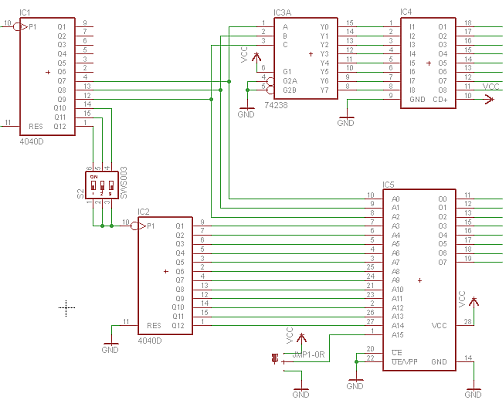
The lower 3 addressbits of the EPROM have to by switched synchronously with the corresponding line on the display. This is achieved by wiring them to a 3-to-8-decoder (74*238) which in turn switches the lines. As up to eight LEDs can light up at once per line. To handle the current an ULN2308A darlington driver is used.

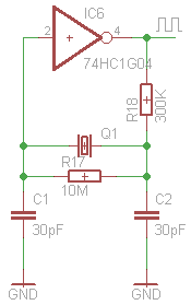
The clock is generated by a crystal oscillator circuit consisting of a 32768 Hz crystal and an inverter gate.
The 32kHz squarewave from the oscillator is then divided by a 12-stage ripple counter (4040). The seventh to ninth stage are used for the line-addressing and are wired to the A0-A2 inputs of the EPROM and to the A,B,C inputs of the 74*238.

Only fourteen addresspins of the EPROM are used, the fifteenth can be set to high or low via a jumper. For more Detail: EPROM Display using ULN2308A microcontroller

