Our final project moves and clicks a mouse cursor on a computer screen by tracking where the user’s eye-movements using infrared eye-tracking technology and a gyroscope.
The motivation for this project came from thinking about applications of infrared technology. We narrowed our ideas down to eye-tracking because of its potential benefit to the disabled and the lack of accurate, inexpensive eye-tracking devices out there.
High Level Design
Rationale:
After researching many eye-tracking devices, we realized that there was a lack of inexpensive and uninhibiting eye-tracking devices.
1. Cost – Most of the eye-trackers we researched used an infrared camera and signal processing software to track the reflection out of the pupil. These systems typically cost hundreds of dollars. Therefore, we decided to go with an infrared LEDs and phototransistors instead of a camera. This method is also much less intensive on our microcontroller than processing video.
2. Range of Motion – The eye-trackers we researched that did not use a camera were all used for medical applications, and as such, had the user lying down or putting their head into a mount. We wanted to make an eye tracker that did not resistrict motion of the head or neck. Consequently, we decided to mount our LEDs on a pair of glasses. This guarantees that the eye is always relative to the head.
3. Vision – Another consideration was how well the user could see using our device. This meant that we would most likely use a transparent lens. To further improve visibility, we would try to use as small components as possible (ideally, surface mount LEDs and phototransistors).
Logical Structure:
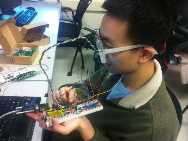
We have a pair of 3-D printed glasses with plastic lenses. These lenses have holes drilled into them to mount thru-hole infrared LEDs and phototransistors. The emitter is positioned above the eye and emits IR light, which is reflected off of the eye into the phototransistors below the eye. We also have a small gyroscope breakout board in the center of our glasses above the bridge, which will detect head movements in three axes of rotation. All of these glasses-mounted components are connected to a microcontroller, which parses the LED and gyroscope data into USART packets and transmits it wirelessly. The packets are read by a wireless receiver on a separate ATMega1284P board, which moves the mouse cursor using a Java program based on the information received. The block diagram below better describes our system:
Background Math:
The primary safety concern is with the radiation from the infrared LED damaging the user’s eye tissue. We researched this very carefully and made sure to purchase IR LEDs with a low intensity and wide profile. Our chosen LED have a maximum radiant intensity of 2.1 mW/sr at 50 mA.
Seeing as how the maximum radiant incidence of the LTE4206 is 1.02 mW/cm^2, and the radiant intensity of our LEDs is much lower than the LTE4206 (0.4 mW/sr vs. 7.67 mW/sr), we can conclude that the radiant incidence of the CQY36N is also much lower than 1.02 mW/cm^2. Therefore, the CQY36N is safe.
Hardware/Software Tradeoffs:
Unfiltered vs. Filtered Data
All of our data input came almost directly from the hardware sensors. After attempting to filter the eye signal, and after attempting to use a Schmitt trigger with hysteresis as an external ADC similar to lab 4, we decided the best method would instead to simply use raw data from the phototransistors. While we realized that we may need to go back and develop a better filter/amplification circuit, we chose to focus this project on the software/microcontroller design aspect rather than the pure hardware signals. Because we wanted to use wireless communication and a gyroscope in our project, we knew that debugging these communication channels and providing an interface with the microcontroller for collaboration between these separate inputs would still be a hefty technical challenge.
3-D Print vs. Safety Glasses
We chose to design and 3-D print our glasses in order to build a product. While we could have borrowed someone else’s glasses design or simply used a pair of safety glasses, we wanted the majority of the project to be design based, so we chose to build a pair of glasses using Solidworks.
Soldering onto PCB vs. Using a Protoboard
§ We chose to cut a PCB and solder a copy of our protoboard circuit onto it rather than simply use the protoboard. Having a final product as a goal, we wanted to make it easy for our future test subjects to wear the microcontroller on their head with the glasses.
Eyetracking Array vs. 2 phototransistors vs. 4 phototransistors
Our original plan was to use an array of phototransistors and LEDs to determine the eye location, but due to the difficulty with which this was to wire and test with, we decided to run tests using simply two phototransistors at first rather than to run tests with so much clutter. We attempted to use an array of phototransistors and LEDs before printing the glasses, and we realized that wiring and layout design would be a major difficulty in testing this sort of system. As such, we designed the hardware and software around 2 phototransistors hoping to improve on this design decision if time allowed. While we were testing our array design, we actually implemented a time based schedule for blinking each LED in the array.
Standards:
Please refer to the Safety section for our standards.
Existing Patents:
For intellectualy property considerations, we researched eye-tracking on Google Scholar and discovered a lot of work has been dedicated to this area. Particularly, a lot of the patents cite concerns for the integration of these systems to current applications. There are some hardware systems currently in development such as the “openEyes” project from Iowa State university , or the Real-Time eye detection project in the 2002 symposium on eye-tracking (Sources in appendix). We will be researching these projects in more detail to get ideas and to make sure that there will not be any additional legal issues with our design.
Hardware
1. Lens
The main purpose of our lens is to hold the infrared LEDs and phototransistors in front of the user’s eye. To determine We first determined where our eyes were in relation to our glasses by securing a piece of acrylic we found in the lab to some cheap plastic frames we already had. Luckily, the plastic already holes in it for our LEDs, so we built a quick prototype and verified with a scope that the phototransistors operated as we expected it to.
The next step was obtaining acrylic and drilling some holes in it to fit our LEDs and phototransistors. We went to Lowes to get cheap acrylic and used a mill in the Emerson machine shop to drill an array of holes corresponding to the user’s eye position.
2. Glasses
We designed our frames in Solidworks and 3-D printed them using a friend’s Makerbot 2. This was a major portion of our mechanical design. Our major design considerations were the internal slots to hold the lenses, small troughs at the top to hold the wires from the infrared diodes, phototransistors, and gyroscope, and a slot in the center to hold the gyroscope.
We printed the frame and the hinges separately because the hinges were too long for the Makerbot printer. After we printed the frame out, we realized that we needed to make all the slots wider; we severly underestimated the width of our plastic lens. Below is the second and final design for our glasses.
In our second design, we made the glasses thicker (0.5 inches), made all the slots wider, and added hollowed extrusions on the sides for the hinges.
Parts List:
| Parts | Quantity | Unit Cost | Total Cost | Source |
| ITG3200 Gyroscope Breakout Board | 1 | $19.95 | $19.95 | Sparkfun |
| ATMega1284P Breakout Boards | 2 | $5 | $10.00 | Lab |
| Power Supply | 1 | $5 | $5.00 | Lab |
| 9V Battery | 1 | $2.00 | $2.00 | 7/11 |
| RCR-433-RP Receiver | 1 | $4.00 | $4.00 | Lab |
| RCT-433-AS Transmitter | 1 | $4.00 | $4.00 | Lab |
| Glasses | 1 | Free | Free | Makerbot |
| CQY36N Infrared LEDs | 10 | $0.52 | $5.52 | Digikey |
| Wires, Resistors, Caps, Inductors, phototransistors, PCB components, connector cables, etc. | Many | Free | Free | Lab |
For more detail: Eye Mouse Using Atmega1284