Summary of Fire Alarm System using AVR Microcontroller
This project outlines a Fire Alert System utilizing an ATMEGA8 microcontroller and an IR-based fire sensor mounted on an SG90 servo motor for 270+ degree coverage. The system detects fire via high pulses from the sensor, triggering a buzzer alarm that can be reset manually. To enhance accuracy, a smoke sensor can be added.
Parts used in the Fire Alert System:
- +5v power supply
- Servo motor (sg90)
- ATMEGA8 microcontroller
- BUZZER
- Button
- 10KΩ resistor
- 1KΩ resistor
- 220Ω resistor
- 100nF capacitor
- AVR-ISP PROGRAMMER
- Fire sensor (IR based)
- Smoke sensor (optional)
In this project, we are going to make a Fire Alert System using ATMEGA8 microcontroller and fire sensor. Fire sensor can be of any type, however we are using IR (Infrared) based Fire Sensor. Although IR based Fire Sensors have some disadvantages mostly of inaccuracy, it is the cheapest and easiest way to detect fire.
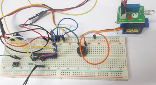
IR Based Fire sensors have lesser sensing vision, so we are going to mount the fire sensor on a servo motor. The Servo will be making 180 degrees pendulum rotations. With the Fire sensor mounted on it, we get a 270+ degrees fire sensing vision. The servo will be rotating continuously thus giving a complete room fire alert system. For more accuracy we can add a smoke sensor to the system. With that we could get higher accuracy.
Circuit Components
Hardware:+5v power supply, Servo motor (sg90), ATMEGA8, BUZZER, Button, 10KΩ resistor, 1KΩ resistor, 220Ω resistor, 100nF capacitor, AVR-ISP PROGRAMMER.
Software: Atmel studio 6.1, progisp or flash magic.
Circuit Diagram & Working
For the servo shaft to move left all the away we need to give 1/18 turn on ration, and for the shaft to rotate all the way to the left we need to give PWM with a duty ration of 2/18. We are going to program ATMEGA8 to give out a PWM signal which will rotate servo shaft to 180 and then to 0 after a certain delay.
During the complete time the Fire Sensor will be on and the controller will be on complete alert. If there is a fire, the sensor provides a high pulse this pulse when detected by controller it sets an alarm. The alarm will be turned off by pressing a reset button which is connected to it. [Also check: Fire Alarm Circuit using Thermister]
In atmega8 for three PWM channels, we have designated three pins. We can only take PWM output at these pins only. Since we are using PWM1 we should take PWM signal at OC1A pin (PORTB 1st PIN). As shown in the circuit diagram, we are connecting the servo signal to OC1A pin. Here another thing is over three PWM channels, two are 8-bit PWM channels and one 16-bit PWM channel. We are going to use a 16-bit PWM channel here.
In ATMEGA there are couple of ways to generate PWM, they are
1. Phase correct PWM.
2. Fast PWM.
Here we are going to keep everything simple, So we are going to use FAST PWM method to generate the PWM signal.
First to choose the frequency of PWM, This depend on application usually, for a LED any frequency greater than 50Hz would do. For that reason we are choosing the counter clock 1MHZ.So we are choosing no prescalar. A prescalar is a number which is so selected to get a lesser counter clock. For example if the oscillator clock is 8Mhz, we can chose a prescalar of ‘8’ to get a 1MHz clock for counter. The prescalar is selected based on frequency. If we want more time period pulses we have to chose higher prescalar.
For more detail: Fire Alarm System using AVR Microcontroller
- Why is an IR based fire sensor chosen for this project?
It is selected because it is the cheapest and easiest way to detect fire, despite some disadvantages like inaccuracy. - How does the servo motor improve the fire sensing vision?
The servo motor mounts the sensor and makes 180 degrees pendulum rotations, providing a 270+ degrees fire sensing vision. - Which pin on the ATMEGA8 provides the PWM output for the servo?
The PWM signal is taken at the OC1A pin, which is the 1st PIN of PORTB. - What method is used to generate the PWM signal in this design?
The project uses the FAST PWM method to keep the setup simple. - What counter clock frequency is chosen for the PWM generation?
A counter clock of 1MHz is chosen by selecting no prescalar. - How is the alarm turned off after detection?
The alarm is turned off by pressing a reset button connected to the system. - Can the accuracy of the system be improved?
Yes, adding a smoke sensor to the system could get higher accuracy. - What software tools are required for programming the ATMEGA8?
The required software includes Atmel studio 6.1 and progisp or flash magic.