Summary of Alarm Clock using ATmega32 Microcontroller
This article introduces an 8051-based stopwatch circuit featuring an LCD display. It highlights the use of the Keil UVision2 compiler for programming, noting it as a highly advantageous and advanced tool for electronics projects. The text mentions availability of Proteus ISIS simulation files and source code for download.
Parts used in the 8051 Stopwatch Circuit:
- 8051 Microcontroller
- LCD Display
- Keil UVision2 Compiler
- Proteus ISIS Simulation Software
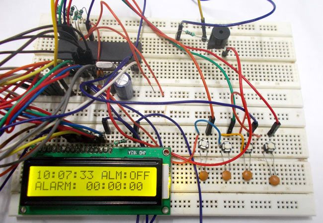
In this project we are going to design a simple Alarm clock using ATMEGA32 timers. ATmega32A microcontroller has a 16 bit timer, and we will be using that timer to count the seconds and develop a digital clock.
All the digital clocks have a crystal inside of them which is the heart of clock. This crystal not only present in clock but present in all computing real time systems. This crystal generates clock pulses, which is needed for timing calculations. Although there are some other ways to get clock pulses but for accuracy and higher frequency most prefer crystal based clock. We are going to connect a crystal to ATMEGA32 for getting accurate clock.
Components Required
Hardware: ATmega32 microcontroller, 11.0592MHz crystal, 22pF Capacitor (2 pieces), Power supply (5v), AVR-ISP PROGRAMMER, JHD_162ALCD(16×2 LCD), 100uF capacitor (connected across power supply), buttons (four pieces), 10KΩ resistor (six pieces), 100nF capacito r(four pieces), Three pin switches (2 pieces), 2N2222 transistor, Buzzer, 200Ω resistor.
Software: Atmel studio 6.1, progisp or flash magic.
Circuit Diagram and Working Explanation 
For accurate timing, we have connected a 11.0592MHz crystal for clock. Now for disabling the internal clock of ATMEGA we have to change its LOW FUSE BITS. Remember we are not touching the high fuse bits so the JTAG communication would be still enabled.
For telling ATMEGA to disable internal clock and to work on external we need to set:
LOW USE BYTE = 0xFF or 0b11111111.
In circuit PORTB of ATMEGA32 is connected to data port LCD. Here one should remember to disable the JTAG communication in PORTC of ATMEGA by changing the high fuse bytes, if one wants to use the PORTC as a normal communication port. In 16×2 LCD there are 16 pins over all if there is a black light, if there is no back light there will be 14 pins. One can power or leave the back light pins. Now in the 14 pins there are 8 data pins (7-14 or D0-D7), 2 power supply pins (1&2 or VSS&VDD or gnd&+5v), 3rd pin for contrast control (VEE-controls how thick the characters should be shown), and 3 control pins (RS&RW&E)
In the circuit, you can observe that I have only took two control pins. This gives the flexibility of better understanding, the contrast bit and READ/WRITE are not often used so they can be shorted to ground. This puts LCD in highest contrast and read mode. We just need to control ENABLE and RS pins to send characters and data accordingly.
The connections which are done for LCD are given below:
PIN1 or VSS to ground
PIN2 or VDD or VCC to +5v power
PIN3 or VEE to ground (gives maximum contrast best for a beginner)
PIN4 or RS (Register Selection) to PD6 of uC
PIN5 or RW (Read/Write) to ground (puts LCD in read mode eases the communication for user)
PIN6 or E (Enable) to PD5 of uC
PIN7 or D0 to PB0 of uC
PIN8 or D1 to PB1 of uC
PIN9 or D2 to PB2 of uC
PIN10 or D3 to PB3 of uC
PIN11 or D4 to PB4 of uC
PIN12 or D5 to PB5 of uC
PIN13 or D6 to PB6 of uC
PIN14 or D7 to PB7 of uC
In the circuit you can see we have used 8bit communication (D0-D7) however this is not a compulsory, we can use 4bit communication (D4-D7) but with 4 bit communication program becomes a bit complex. So as shown in the above table we are connecting 10 pins of LCD to controller in which 8 pins are data pins and 2 pins for control.
Switch one is for enabling adjust feature between alarm and time. If the pin is low, we can adjust alarm time by pressing buttons. If its high buttons are for adjusting just TIME. There are FOUR buttons present here, first is for increment MINUTES in alarm or time. Second is for decrement MINUTES in alarm or time. Third is for increment HOUR in alarm or time. FOURTH is for decrement HOURS in alarm or time.
The capacitors present here is for nullifying the bouncing effect of buttons. If they are removed the controller might count more than one each time the button is pressed. The resistors connected for pins are for limiting the current, when the button is pressed to pull down the pin to the ground.
Whenever a button is pressed, The corresponding pin of controller gets pulled down to ground and thus the controller recognizes that certain button is pressed and corresponding action is taken.
First of all, the clock we choose here is 11059200 Hz, dividing it by 1024 gives 10800. So for every second we get 10800 pulses. So we are going to start a counter with 1024 prescaler to get the counter clock as 10800 Hz. Second we are going to use the CTC (Clear Timer Counter) mode of ATMEGA. There will be a 16 bit register where we can store a value (compare value), when the counter counts up to the compare value an interrupt is set to generate.
We are going to set the compare value to 10800, so basically we will have a ISR (Interrupt Service Routine on every comparison) for every second. So we are going to use this timely routine to get the clock we needed.
For more detail: Alarm Clock using ATmega32 Microcontroller
- What is the primary microcontroller used in this project?
The project uses an 8051 microcontroller. - Which compiler is recommended for programming the 8051 in this circuit?
The Keil UVision2 compiler is identified as the most advanced and advantageous option. - Does the circuit include a visual output component?
Yes, the circuit features an LCD display for showing stopwatch data. - Can I simulate this circuit before building it?
Yes, Proteus ISIS simulation files are available for the project. - Where can I find the source code for this project?
Source code files are provided in a downloadable archive named 8051-stopwatch-circuit-with-lcd-display.rar. - Is this project suitable for beginners looking for easy tools?
The text suggests choosing the easiest and most advantageous options like Keil for such electronics projects.