Summary of Flat Bed Scanner Using Microcontroller
This article details a DIY flatbed scanner built from scavenged materials for under $40. The project uses stepper motors and threaded rods for precise X-Y movement, controlled by an MCU. A QRB114 phototransistor scans pixels one by one, while cannibalized mouse sensors provide home positioning. The system outputs black-and-white images to a TV via video interrupts, utilizing software-controlled motor stepping and various scanning modes like zig-zag.
Parts used in the Flat Bed Scanner:
- Threaded Rods
- MCU
- Sheet metal
- Bolts
- Solder boards
- Gears
- Wood
- QRB114 sensor
- Brackets
- ULN2003 drivers
- LMC711 op-amps
- Glue and screws
Introduction
Quite possibly the slowest and lowest resolution of any scanner on the market today, but it sure is mesmerizing to watch.. and it actually works!
That’s about the best way to describe this behemoth of a project, which involved countless hours of building, gluing and scavenging for parts.
The goal we strived for was to create a useable scanner that outputted to the TV and possibly data serially to the PC, in black and white with the ability to do some gray scale. We were able to reach the goal of outputting the resultant scan to TV in black in white, but due to large amount of man hours spent on the mechanics of the device and to make the device run entirely independent of any lab equipment, we didn’t implement the serial connection. The scanner does have the capability to output grayscale to PC.. if we ever have to time add it.
“We choose to go to the moon in this decade and do the other things, not because they are easy, but because they are hard,”
– John F. Kennedy in September 1962.
So our project isn’t anywhere near as difficult as landing on the moon, but we decided to delve into a very mechanically driven project because of all the challenges we faced. One of the largest challenges being the utter lack of proper tools to make precise cuts, measurements etc. A second challenge that makes the project incredibly entertaining is that the device used to detect the darkness of a pixel of the image, represents only 1/40 of the budget.. we spent $1.29 on it. With these factors in mind we are very pleased with outcome and results of homebuilt scanner.
High Level Design
Many will probably wonder where this crazy idea and design for a scanner came from. Well it developed in Andy’s mind about 6 years ago, when he owned a Lego Mindstorms and read on some random website about how some user had developed a scanner. After only see a very small dark image of what the scanner looked like he made a valiant attempt to create his own scanner with his extensive collection of Legos. Unfortunately not enough Legos were to be found and the design and the idea were left to collect dust. Till one day..
Then came along the 476 ECE Final Project where the idea jumped back to life but this time it would be designed out of scrap parts and every aspect built or written and tested thoroughly.
The way in which the scanner actually goes about scanning is an incredibly essential and very well throughout method. In a traditional scanner the actual scanning sensor is a fix width wide and as a result only requires one fixed pass of the image (i.e. moving vertically across the image) to scan in the entire image. Now maybe if we had really searched around and begged for samples we might have received one of these wonderful scanning sensors, but instead we decided to opt for the $1.29 solution of a Phototransistor reflective object sensor (QRB114). This meant that the sensor would be reading one pixel at a time which implies that our design would have to move both in the vertical and horizontal direction. The upside of this design is that we could, at least in theory, scan any imaginable size image (actually the area scan-able is approx. 12in by 9.4in). Unfortunately there are a few large downsides to this method; It is very slow and all this back and forth movement requires rather precise control of exact position of the scanner head.
We couldn’t really do much about the slowness other than try to create faster ways to scan, like the zig-zag method as we call it, where you take sensor data as the sensor head moves in the positive direction, then when it hits the maximum x distance you move the y distance down one and take sensor data as the sensor moves back to the starting x position.
To maintain precise position of the sensor head we implemented a rather clever design, at least we think it is clever and probably the coolest part of the whole project, the treaded rods and gears connected to stepper motors. The threaded rods are nothing but incredibly long screws, which can also be visualized as a very large gear that has had the teeth on the circumference laid out in a straight line. Therefore the actual gears can move with great precision on the threaded rods and we can maintain a more discrete way of representing distance in the x and y direction. To create this discrete positioning also required the use of stepper motors. The stepper motors used in this lab where some remaining ones from years before, with little documentation but luckily due to The Postage Meter Project (sp 2002), we were able to hook them up and after some rudimentary work determine that the angle was 15 degrees which made the half step 7.5.
We made the determination that we would do all the stepping of the motors in software which at the time of writing this might have been a slight mistake considering the motors after hours in operation are occasionally acting rather odd.
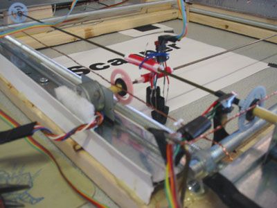
With the x y position figured out we had to hook the sensor onto the crossing of the x and y axles (which are just coat hangers), this turned out to be a major headache which required a couple different gluing attempts and a lot of jerry-rigged wire setups to hold the sensor in place. (See image below showing a blue wire holding sensor in place)
The final piece of the design was the use of cannibalized mice position sensors. We used these sensors to define the starting (home position) for both the x and y direction. We realized that we need some specific location to start scanning from especially given the fact that every time we reset up the scanner the gears and the axles had shifted way out of whack.
Below is a simple diagram as to how we mapped out how the software would function in this lab.
The intent was to create a simple user interface with buttons that allowed the user to select a resolution of scanning and a possible mode.
Types of tradeoffs involved:
We could have implemented the stepper motor control in hardware which would have required more logic which might have implied another solder board (I think 3 is enough) and may have save some of the painful determination of which brush to run next depending on if the motor is now going forward or backward.
There really isn’t much that we built in hardware that we could implement in software, except maybe make the mouse sensor outputs feed straight into the ADC, but this would have slowed down the scanner even more and we think the op-amp setup we created is more superior since it converts the analog signal to a TTL logic level.
Hardware Design
Now to the real meat and potatoes of the project. The actual building of the scanner. We salvaged the wood from a crate behind Thurston and much of the metal came from ceiling tile anchors found behind Phillips. The mouse sensor were collected from old mice that were no longer useful, and other parts of the mice were incorporated into the axles for movement. The threaded rods were cut by hand which ended up taking about 30 minutes and a lot of brute strength.
Glue and screws were used throughout the project to hold all different types of materials together, and copper wire was utilized to hold the gears and axles in place. A part of a pen and some straws were utilized in creating the holder for the sensor. Of all the task required to create the physical portion of the scanner it was the gluing that was the most frustrating and time consuming. Certain types of glue would not bond two types of plastic together and super glue is totally useless since it doesn’t bond fast enough to be used to bond a metal screw to plastic.
The scanner is pretty close to square, off by a little under 1/8″ which is decent considering the inaccuracy in every cut we made. For the most part there was a very general idea of what the scanner was to look like which was highly dependent on what materials we could actually come upon to use.
If someone would like to build a scanner of similar attributes as this one feel free to contact Andy Hocker[email protected] for more info, it would be to tedious and also too confusing to explain on a web page. But for a little more clarity we have included some photos of the scanner with some of the important areas focused on.
One can see the infrared sensor (mouse sensor which is glowing purple) and the incredibly fine detail of the threaded rods and gears as they move over the metallic surface, which happens to be one of the ceiling tile pieces.
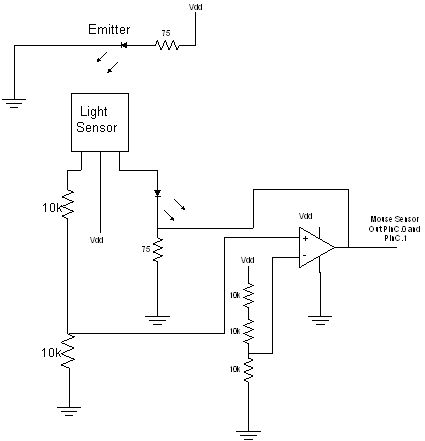
The actual electrical hardware was rather easy to build. The mouse sensors were the hardest to setup since we had no idea what the pin layout was. But after blowing one device out we were able to establish the layout and then made the decision that if we used an op amp for comparison we could convert the output to TTL logic level which would make using these sensors in our project easy and also would make it incredibly fast to determine if one of the axles had returned to its starting position. To compare we had to fool around with voltage dividers until we found a happy combination that would activate the sensor in an acceptable manner. A really cool trick that helped us determine if our infrared diodes were on was that the diodes glowed green to white in my camera cell phone, actually any CCD, which made it much easier to setup the corresponding sensor. As can be seen from the above picture the sensor is basically held together with superglue, a portion of a straw, some electrical tape, and some hot glue.
The sensor for light and dark detection was even easier to build. After a little searching about how the device worked we came to establish a setup that would magnify the output of the sensor by a factor two which seemed to yield a very good range of white being near 4.5 Volts and black at around 0.9Volts. We then could use AREF as the comparison for the ADC for establishing the color of the pixel.
The schematics in the schematics section are a good reference for building the above circuits.
From here we first made all of our circuits on protoboards to test and then converted the whole setup to solder-boards.
The Hardware design was a lot of hard work and a lot of trial and errors, even with the scanner in a very good working state we still occasionally have some mechanical glitches and errors and are constantly fixing and mending the mechanical pieces of the project. We have a much deeper respect for mechanical engineers and all the headache that goes with creating a reliable design.
Program Design
To more easily manage our code, we divided it into 4 files.
finalproc.c contains the main program loop
xymotors.h contains functions that control the forward and backward movement of the stepper motors
video_int.h contains the video interrupt, written by Prof. Bruce Land
video.h contains the video code written by Prof. Bruce Land
Our main program loop first waits for input from the user. The program starts out in full-stepping mode, which will scan nearly an entire sheet of paper. The user can also press the half-step button to have the scanner perform over a smaller area with better resolution (motors will operate on half-steps). The program will wait until the user selects a scan mode: one-directional, zig-zag with slowing, and normal zig-zag. Because the output is sent to a TV we have a set image size that we can display, being that each pixel is simply a bit either being on or off we have the max screen size of 128×100 pixels. As a result all the scan modes use up all this space, so at full-stepping speed the screen area covered is twice as large as when the motor is half-stepped.
Before the image starts to scan the sensor first calibrates by looking at a totally white square and then moves to a totally black square, it then sets the threshold between black and white at exactly the mid point between the two values. It might be better to set the threshold closer to white since after a lot of testing it is apparent that the sensor is more sensitive to white on black than black on white…(will be explained later)
First, we must explain that our scanner was programmed so that the sensor scans along the x axis and steps along the y axis. That is, the x axle and motor constantly move back and forth while the y axle and motor moves only one step forward each time the x motor comes back to its starting point.
When it actually takes sensor data for a point we first sample the ADC three times with a 1ms with of delay between them, then we take the value that occurred 2 or more times either black or white, and set the pixel as that value.
In one-directional mode, the scanner only samples the image when moving in the positive x direction. It then moves the sensor all the way back, and then steps in y. This method is the slowest, but typically provides a less distorted image as our zig-zag methods have a tendency to skew the image. This mode also has the slowing feature in that the x motor slows down when it reaches near both ends of a line. This feature was implemented to reduce the sensor shaking that occurs when the motor switches directions.
The zig-zag with slowing mode samples the image on both the forward and backward movement of the x motor. This effectively doubles the scan speed from the previous mode. However, an inherent problem that occured with zig-zag scanning was that the scanned lines displayed on the TV were systematically misaligned. We thought that this might have been attributed to the angle the sensor is pointing at the image surface (it is not exactly 90 degrees) and the different directions of movement of the sensor. We compensated for this problem by having the x motor take a couple pre-emptive steps just before it started its backward-movement loop. This way, we were able to re-align the screen line samples from both forward and backward movement.
The normal zig-zag mode is simply the same as above but without slowing at the edges. This was so we could compare image differences with the slowing feature.
Each mode goes through a similar loop structure that samples, puts to the video buffer, and detects user reset, detects TV display button, and steps the motor.
The trickiest part of writing the code was getting the proper motor brush scheme setup for when the motor would move from forward to backward, without this the motor would act unreliable and could slip and distort the image worse than it already is.
Parts List:
| Threaded Rods | $4.40 |
| MCU | $8.00 |
| sheet metal | $1.26 |
| 12bolts $0.06 each | $0.70 |
| 3 solder boards | $7.50 |
| 1 small solder board | $0.80 |
| glue and screws | $4.00 |
| Gears | $1.60 |
| Wood | Free |
| other metal | Free |
| QRB1114 | $1.29 |
| Brackets | $2.80 |
| ULN2003 (2) | $1.28 |
| LMC711 (3) | $4.50 |
| other components | Free |
Total: $37.73
For more detail: Flat Bed Scanner Using Microcontroller
- How does the scanner detect image pixels?
The scanner uses a QRB114 phototransistor reflective object sensor to read one pixel at a time. - Can the device output data serially to a PC?
No, the serial connection was not implemented due to the extensive man hours spent on mechanics. - What method is used to move the sensor head precisely?
Stepper motors drive threaded rods and gears to maintain discrete positioning in the x and y directions. - How does the zig-zag with slowing mode improve scanning?
This mode samples data during both forward and backward movements while slowing down at edges to reduce shaking. - What is the maximum screen resolution for the output?
The maximum screen size is 128x100 pixels since each pixel is simply a bit being on or off. - How does the scanner determine the starting position?
Cannibalized mice position sensors are used to define the home position for both axes. - Does the hardware control the stepper motors?
No, all stepping of the motors is done in software rather than hardware logic. - What is the total cost of the project?
The total cost for all parts listed in the project is $37.73.