Introduction
Our project is a digital stethoscope that displays your heartbeat on any television. It also calculates beats per minute and alerts you if your rate falls out of a specified range.

At the highest level, the design of our project centers around an acquisition circuit, data processing in two MCUs, and the output on a TV screen. The first part of the stethoscope is the acquisition unit, which consists of an actual stethoscope mated with a microphone, and an amplifier circuit. The microphone captures the audible signal from the body that is acoustically amplified by the stethoscope. After that, we bias and set the gain of the signal using an operational amplifier so that the ADC on the MCU will be able to pick up the signal.
The analog data will be independently sampled by the two MCUs at a rate appropriate for display on the TV (CPU1) and a rate sufficient to capture the appropriate characteristics of the signal for beat detection (CPU2). CPU2, uses a moving threshold scheme to detect the actual heartbeats, and from that derive the heart rate. Then the signal is blasted to the TV, which also displays pertinent data, such as beats per minute. Additional information is displayed on the HyperTerm. If applicable, a buzzer will sound if your heart rate falls out of a specified range.
High Level Design
The Idea and Requisite Knowledge
The idea for our project is pretty much our own, and is really just a proof of concept and a good demonstration of the capabilities of the Mega32. There are many instruments commercially available to measure your heart rate, even with far greater accuracy than we obtain. We thought it would be interesting to implement a usable piece of equipment that puts the heart rate on the TV and gets the correct beats per minute (BPM) reasonably well.
There is no requisite knowledge to understand our project beyond the content of ECE 476, except maybe that of low-pass filters. Our acquisition circuit contains an analog low-pass filter and the second MCU which calculates the actual BPM uses a digital low-pass filter also. The characteristics for the analog filter and the math for the digital filter appear in the program/hardware design section, where they can be viewed in context. It is also good to know that there is a major spike for each heartbeat.
General Design
In our final project we implemented a digital stethoscope. At the highest level, the design of our project centers around an acquisition circuit. Data processing in two MCUs, and the output on a TV screen. The stethoscope detects and displays the heart beat and BPM. The first part of the stethoscope is the acquisition unit, which basically consists of an actual stethoscope mated with a microphone, and an amplifier circuit. The microphone captures the audible signal from the body that is acoustically amplified by the stethoscope. After that, we set the gain of the signal using an operational amplifier so that the ADC on the MCU will be able to pick up the signal. This is necessary because the amount of signal you get from the heartbeat in your neck is probably much more than the heartbeat in your wrist. For example.
The analog data will be independently sampled by the two MCUs at a rate appropriate for display on the TV (CPU1) and a rate sufficient to capture the appropriate characteristics of the signal for beat detection.
(CPU2). With uniform data to work with in CPU2, we then wrote a scheme to detect the actual heartbeat, and from that derive the heart rate. There are many methods we could use to implement this including absolute minima/maxima, average min/max, and Fourier (frequency) representation of the signal. Our basic approach uses a moving threshold approach that is outlined in detail in the software section below. The heartbeat signal and rate (beats per minute) will then be output to the TV screen, similar to ECE476 lab 4. Figure 1 shows the basic setup of the entire project.
Hardware/Software Tradeoffs
One example of a hardware/software tradeoff in our project was our decision to eliminate automatic gain control. We included this feature in our proposal because it would improve the robustness of the digital stethoscope by increasing the number of areas on your body that you could take a reading. (ie. The signal from your neck is different from your wrist.) Basically, when we deemed hardware AGC too difficult, we decided to implement it in software.
However, it turned out that we really didnt need it at all, since the output from the acquisition circuit on the neck was relatively stable and consistent, even with different users. We could have just blown the output of the microphone up in software, but we decided to use an op-amp to obtain resolution on the analog to digital conversion. Also, the beats from weaker points on the body, like the wrist, just did not come out looking like beats at all.
Another tradeoff was the way that we implemented the mute function for the alert buzzer. Instead of having a few logic gates hanging off of the high and low violation control lines between the two CPUs, we decided to implement the logic inside the second MCU and just have an extra output for the buzzer. This saved extra external hardware, but added a level of complexity to the code. In general, we tried to implement as much as possible in software, when appropriate.
Another limiting factor of the Mega32 CPUs is that they have a finite number of I/O ports. Since we have 2 CPUs (one for displaying information, one for computing information), there is a limit on the amount of information that we could output, on the TV especially. Because we essentially had more numbers to put on the TV than we had I/O ports to send it between the CPUs, we decided to implement the RS232 interface to HyperTerminal on the PC.A picture of the output on the HyperTerminal can be found in the appendix.
Recognized Standards
The first standard in use for our project is the same we used in ECE476 lab 4, the RS170 composite video standard and the NTSC frame rate. Our TV signal is non-interlaced, black and white video just as in lab 4. The RS170 standard dictates the 3 voltages for black, white and sync, as well as the 4:3 aspect ratio, and the widths of the horizontal and vertical sync pulses and their front and back porches. Additionally, the RS170 standard dictates that there are 525 lines per frame, and 60 frames per second. As described above, our implementation uses a 30fps, non-interlaced version.
The second standard that we used was RS232 serial interface with the PC. RS232 is a common serial interface for digital data communications. It specifies signal voltages, timing, and protocols for information exchange and mechanical connectors. Because our RS232 was implemented on the STK500, we did not have to touch any of the specifics of the protocol as the Mega32 implements it for us.
Patents and Intellectual Property
There are already many methods of detecting heart beat patterns and pulse rates. Undoubtedly many of these methods are protected under patent law, but the simplicity of our design will not encroach on any of those complex designs. There are many patents on stethoscopes. While we are using one, however, we are not designing it. This will probably limit the chances of our device receiving a patent. Really, the only patent potential our device has is the fact that it plugs into your own TV.
We also feel that credit is due to others for part of the code used in our CPUs. This will also limit our patent potential. Professor Bruce Land of Cornell University supplied the basic code for NTSC video output on the Mega32 in the ECE476 lab 4. We use an altered version of this code in CPU1 which outputs the heartbeat signal to the TV. Also, the majority of the button debouncing state machine in CPU2 was also supplied by Dr. Land in the ECE476 lectures. A general diagram of the state machine can be found in the Appendix.
Program/Hardware Design
Hardware Details
The first part of our circuit was the stethoscope itself. Aarons father is a cardiologist and we were able to obtain a used stethoscope from him free of charge. Originally the stethoscope had very flexible medical latex tubing which mated the end piece with the metal frame and the earpieces.The problem with the tubing is that we could not find a microphone small enough to fit inside it. Our solution was to make a trip to the hardware store and pick up some vinyl tubing. We used 3/16 inside diameter tubing for the main length and then 2 fitted larger sizes to telescope up to the size of our microphone.
After we worked the microphone down into the largest piece, we secured it with a metal hose clamp, as shown in figure 2. We initially figured that the tube needed to be sealed so that acoustic loss would be minimized. We attempted to melt the pieces of tubing together, but that was quite disastrous and we ended up burning holes in the tubing. Eventually decided (after reassurance from Professor Land) that it was adequate to just jam the pieces together.
The WM-034DHB microphone we used is omnidirectional with -42dB sensitivity, >60dB SNR, and a 20-16kHz response range. This particular microphone requires a 1.5V bias to operate properly. We built a bias circuit using a 10kΩ trimpot, a 2N3904 NPN transistor, and a few resistors. The diagram for the microphone bias circuit is shown in figure 3. The gain portion of our circuit consists of an LMC7111 op-amp set up with a gain of 7, in a low-pass configuration, as shown in figure 4. For this circuit, the equations for the low-pass time constant and amplifier gain are as follows:
![]()
![]()
We used an actual time constant of 0.5 and a gain of 7, as shown in figure 4. The input of the amplifier was coupled to a DC voltage of around 2.5V. This was necessary to center the amplified signal in the A/D range for the MCU.
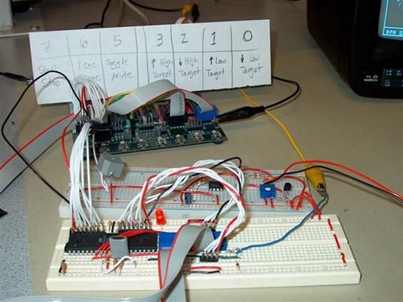
Since we use two MCUs (as detailed in the software details section), we had to build one MCU setup on a white board. Figure 5 is a photograph of CPU1 and the TV output circuit on the white board (The MCU and TV circuit are on the lower of the two whiteboards shown; the upper is the microphone bias and amplifier circuit, along with the buzzer). The TV uses pin D.5 as the sync signal, and D.6 as the video input. HyperTerm was set up by connections from the STK500 to the PC, D.0 was the receive bit and D.1 was the transmit bit. Please refer to the appendix for a picture of the actual Hyperterm output. The TV output DAC, shown in figure 1, was provided to us in ECE 476 lab 4. The appendix contains a detailed diagram of how the Mega32 is implemented on the whiteboard.
The final piece of hardware we used was a CT-1205C buzzer, which is shown on the upper board in figure 5. This is used to indicate a violation of the high or low BPM violations. We bought this particular buzzer because it was loud, annoying, inexpensive, and could be driven off of a single output pin in terms of current and voltage.
Software Details
Initially we planned on using only one MCU, but we quickly realized that it just was not possible to do all the necessary calculations and blast output to the screen on one MCU. The 2-CPU solution we came up with uses CPU1 for the TV output, and CPU2 as a processing unit. Both CPUs sample the same heart beat signal independently of each other and at different rates.
Our CPU1 code was a modified version of our ECE476 lab 4 code, which in turn was a modified version of Professor Lands code for NTSC video output from the Mega32. Similar to lab 4, the TV (CPU1) has different timing modes, and can be set to display either one or two seconds of trace across the screen. We decided to go with the one/two second division because at 60BPM, a typical heart rate, there is exactly one heartbeat on a one second width. With a two second width, of course, you can see at least two complete beats.
CPU1 also takes several control lines that are generated by CPU2, including high and low violation lines, run/stop and one/two second screen widths from the buttons attached to CPU2. Finally, there are 8 parallel bits which transmit the beats per minute as they are calculated. Figure 1 shows how the two CPUs fit together and interface, along with outside connections. The following table (figure 6) outlines the various definitions for the interface and control lines.
CPU2 has three basic tasks. First, it is responsible for debouncing the 7 buttons attached on port B. We used a state machine structure that was similar to the one presented in ECE 476 lecture for debouncing buttons. The button functions are outlined in the following table, and a general diagram for a debouncing state machine can be found in the Appendix.
Second, CPU2 is responsible for calculating the BPM of the sampled signal. We chose to go with a windowed sampling scheme, instead of a real-time approach. This basically means we take a string of samples over a certain time period, process the data, determine the BPM, and start the next sample string. In order to cover the reasonable BPM ranges of the human cardiovascular system, we were aiming for reliable performance between 60 and 180BPM. The low end is where we really had to worry since at 60BPM, there is one beat each second.
Our detection scheme basically attempts to find pulse peaks in the data, determines the time between the peaks, and then converts that to BPM. The sample window had to be long enough to get at least two beats in one window for the lowest range.At 60BPM, a 2 second window gives this, and this is the window we chose. The downside to the long sample window is that we can only provide a new BPM update every 2 seconds. This decision between sample window length and the rate at with the BPM is output is a tradeoff that we made. Heart rates lower than 60BPM can be detected if two pulses happen to fall inside the 2 second window, but since the phase of the beats is relatively random, there is no guarantee this will happen.
We modified our code such that if we only identified one peak, we would leave BPM unchanged. If we didnt identify any peaks, then BPM was set to 0. In the lab, we were able to reliably detect heart rates of around 50BPM. The high end accuracy was limited by how much time we waited after identifying the first peak before looking for the second peak. Our code waits 150 samples at 2ms each, or a total of 300ms, which equates to a maximum of 200BPM.
The beat detection algorithm is actually quite simple. We took 1000 data points over 2 seconds, giving a sampling rate of 2ms. This corresponds to a sampling frequency of 500Hz. The Nyquist Sampling Theorem states then that the largest frequency component present in our sampled signal is 250Hz. This in effect is a low pass filter. This is not a problem, however, since we are only interested in the low frequencies anyway. A second digital low-pass filter was implemented as a weighted rolling average. The filter looks like this:
The alpha value in the equation dictates the amount of smudging that occurs. This in effect smoothes the data and lowers the noise floor. We experimentally determined the best alpha was 0.8. The resulting 1000 data points in CPU2 then would look something like figure 8, which graphs actual data we collected by printing it to the HyperTerm. Before sampling and the digital low-pass filter, the SNR of the heartbeat signal was about 5, but you can see from figure 8 that the post-filtered SNR is much higher. The detection uses a moving threshold algorithm. The first step is to determine the maximum value of data in the sequence. Then, we look for successive peaks with increasing slopes within 80% of the maximum value. This inherently assumes that the peaks in the input sequence are relatively stable, and within a reasonable range above the secondary peaks and noise.
The third function of CPU2 is to send data to CPU1 and to control the alarm buzzer. CPU2 sends BPM through PORTC and information about the modes of operation and violations through PORTA to CPU1. CPU2 sends one bit to the buzzer for violations through PORTA. Figure 1 shows the specific connections and figure 6 outlines the control lines. In addition to the data sent to CPU1, the second CPU also outputs other (excess) data to the HyperTerm. This includes the maximum value (out of 255) received over the last sample window, the indexes of the two beats used to determine the BPM, the actual BPM, and the high and low threshold values which are settable by the buttons attached to PORTB. The data is updated every 2 seconds, just like the BPM value. Typical HyperTerminal output is shown in the Appendix.
Things We Tried That Didnt Work
Our project was very successful as a whole, but there were a few things that did not work out as we had originally planned. First, we planned to display the high/low violation values on the TV. The problem with this is that the buttons to set the high/low values are attached to CPU2 on the STK500. We did not have enough output ports left to send two 8bit numbers to CPU1. Because there was no easy way to synchronize the CPUs we settled on using HyperTerm to display the high/low violation values. We did, however, print HIGH or LOW on the screen if the respective violations occurred.
Second, we wanted to blast the digitally filtered heartbeat signal to the television. The filtering would have to be done on CPU1 since there is too much data to transfer it from CPU2 to CPU1. Since the trace on the TV rolls across the screen, a significant amount of logic had to be inserted to keep track of the edge of the data trace. The filter would need to start on the edge, wrap around the screen and continue back to the edge so that the data is filtered in order. When we implemented this, the code was just too bulky, and interfered with the timing of the TV output. We decided to settle for displaying the heartbeat signal that was amplified and filtered in an analog fashion on the television.
Lastly, we wanted to implement automatic gain control (AGC), but realized that it was not very useful or necessary.In addition, it is nice to see the relative strength of different heartbeat signals. This was explained in the above section, Hardware/Software Tradeoffs.
Results
Speed of Execution
In CPU1, our digital stethoscope draws the heartbeat trace to the television with a delay imperceptible to humans. Since CPU2 uses a sampling window to determine the BPM, there is an inherent 2 second delay between updates of the heart rate. The HyperTerm is updated every 2 seconds as well. All other components of our project execute with no perceptible delay and no concurrency issues ever arose.
Accuracy
Our design was able to achieve a good level of accuracy, considering the cheap parts used and simple structure of design. The signal to noise ratio for the amplified input (which was then sampled), was around 5:1, so the heartbeat displayed on the screen looks good. Figure 9 shows a typical trace on the TV screen. On occasion, some stray pixels were left on the screen, probably due to the timing of our CPU1 code. We were not able to entirely eliminate this, but it does not happen very often and we modified the code to solve this problem and make it happen as seldom as possible. When the digital stethoscope is put into stop mode and then started again these imperfections are cleared when the screen is initialized. On the whole, though, our trace is of very good quality, as is demonstrated below.
Accuracy for our BPM calculation was discussed in the software design section. In general, we found that our digital stethoscope was accurate in the range of around 50-180 BPM. We used a function generator to help determine these bounds. In addition, BPM is calculated every 2 second from the time between two successive peaks and then that time per beat is converted into BPM. Consequently, the actual BPM is only updated every 2 seconds.
Our digital stethoscope works most reliably with a strong heartbeat signal. If a signal is not very strong, it may be hard to detect peaks because of inherent noise. Thus, on a few occasions, we found it necessary to get out of our chairs in the lab and run up and down the stairs a few times to keep our blood moving. Its quite amazing how much this makes a difference. Finding the right place for the end piece of stethoscope is also very important. The strongest and most reliable place on the body that we found was the neck.
We had limited success on the heart when blood flow was good. The wrist rarely worked at all. Additionally, you must be very still and quiet to use our device. Talking or movement of the stethoscope produces output far above the voltage rail of the amplifier, and the resulting heartbeat trace and BPM will not be displayed accurately. This is however inherent to any stethoscope and not unique to our project; if an old-fashioned stethoscope moves around or the patient talks when it is on his/her neck there will be mostly noise.
Safety Enforcement and Interference
Our design is inherently safe for several reasons. First, the only contact our device has with the user is the end piece of the stethoscope; it is placed against his/her neck or chest. This is as safe as using a normal stethoscope. Additionally, we use no high voltages or currents in any of our circuits. Humans are protected from this anyway since the plastic tubing connecting the microphone and the stethoscope end piece are insulators and do not conduct any current.
Our chip to chip communication is purely wired, so our design does not interfere in any way with other groups designs.
Usability
Our digital stethoscope is easy to use. The most difficult part of using the digital stethoscope is to find the best place to measure your heartbeat. This is typically on your neck, but the chest as also well has worked in the lab. Additionally, people with heartbeats that are not very strong will have a harder time finding the right place and getting a good display of their heartbeat on the television. If you are having trouble getting a good display of your heartbeat, you can always run up and down the stairs or do something equivalent to raise your heart rate and blood flow. The increase in heart rate and stronger beats will make a better display.
Others ECE 476 students have had no problems working our project after a simple explanation; our design is user friendly.
[ Back to Top ]
Conclusions
Analysis of Results
We were very happy with the final results of our project. The finished product met our expectations and worked as well as we could have hoped. Our project demonstrates what can be done using Mega32 MCUs with some additional circuitry and components. The display of the heartbeat is very good and the BPM calculations are accurate for a wide range of heart rates. The proper placement of the end piece on the bodyin order to get a good signalcan be finicky at times, but with some practice, you can find a good spot easily, and it will give excellent results.
If we had more time, there are some additions to the project that we would attempt. First, we would try to improve the low end BPM calculation accuracy, without delaying the BPM displayed on the television when unnecessary.We would try to go about this by altering when we stored ADC values in the array, so that the peak of the heartbeat would be near the beginning of the array and the beat would be properly detected. Second, we would try to make our digital stethoscope work from more points on the body.
This would likely entail implementing additional amplification for certain parts of the body and possibly additional filters for different sources for noise. Third, we would try to output a smoother signal on the television, similar to the signal we used calculated BPM. It was not implemented in our project because it screwed up the timing, but we may be able to implement it, although it would be difficult, if we spent significant time and modified some of the structure of our CPU1 code.
Standards & Intellectual Property
As discussed above, much of the TV output code inside CPU1 was provided for us in the ECE476 lab 4 by Cornell Professor Bruce Land. Additionally, the debounce state machine for the buttons attached to CPU2 was derived from Professor Lands lectures. Other than that, the code used in this project is of our own design and is not part of the public domain. Our design is a simple and interesting implementation of a digital stethoscope, but we do not feel that there are any patent opportunities because commercial solutions are much more specialized and specific, and patents are very expensive to obtain. Because of the general nature of our project, we do not feel that we infringed on any other existing intellectual property.
Ethical Considerations
In all stages of design, implementation and testing, we complied with the IEEE code of ethics. Five points from the IEEE code of ethics are referenced below, followed by an explanation of how we complied with them.
Point one: To accept responsibility in making engineering decisions consistent with the safety, health and welfare of the public, and to disclose promptly factors that might endanger the public or the environment.
Our project is safe and users are not at risk when using our digital stethoscope. The digital stethoscope can alert the user through a buzzer if his/her heart rate falls outside of a safety zone that the user can define. Also, a trained professional may be able to identify problems with heartbeats by viewing the display from our project onto the television. Our project works to promote health and welfare of the public and does nothing to harm people.
Point three: To be honest and realistic in stating claims or estimates based on available data.
From the beginning, we had a realistic view of the project in mind and set goals accordingly. We made every possible effort to obtain reliable data and report it in an objective fashion. We stand behind all claims in this report, as they are honest and reliable.
Point seven: To seek, accept, and offer honest criticism of technical work, to acknowledge and correct errors, and to credit properly the contributions of others.
On this website, we have properly credited the contributions of others. At several points in the project, we asked Professor Land his opinion about what characteristics are most important for our microphone or how to make a circuit better when we wanted the opinion of someone with more experience and expertise. This advice and criticism helped to make our project better, and we are grateful for it. There were also errors made in our project, such as incorrect connections or flawed code, but all the errors we encountered were acknowledged, debugged and fixed.
Point nine: To avoid injuring others, their property, reputation, or employment by false or malicious action.
No one was injured in any way during the completion of the project. We were respectful of others property, space, and need to use lab benches.
Point ten: To assist colleagues and co-workers in their professional development and to support them in following this code of ethics.
During this project, our colleagues and co-workers were fellow ECE 476 students and our partners. We tried to be as helpful as possible when other groups asked us questions or showed us their projects. The project was completed earlier and the end result was better because we worked together as a group and had high standards for each others work. In addition to assisting in professional development, we also supported each other in following the IEEE code of ethics. For example, we made a conscious effort to both make sure we presented our project honestly and objectively and cited sources properly.
Parts List:
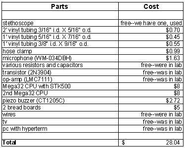
For more detail: Digital Stethoscope Using Atmega32