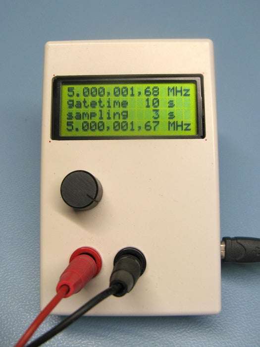
Summary of Frequency Counter With Variable Gate Time
This article details a reciprocal frequency counter built on an STM32F103C8 (Blue Pill) featuring selectable gate times from 0.1 to 60 seconds and a measurement range up to 10 MHz. The design ensures input safety for 3.3V and 5V signals while utilizing a high-precision 10 MHz OCXO and a D-flip-flop for accurate triggering.
Parts used in the Frequency Counter:
- STM32F103C8 (Blue Pill)
- 16 x 4 LCD screen (HD44780 compatible)
- 10 MHz OCXO
- 74HC74
- 74HC00
- 3.3V voltage regulator
- Rotary encoder with button
- Resistors, capacitors, and diodes
- Perfboard
- Project box
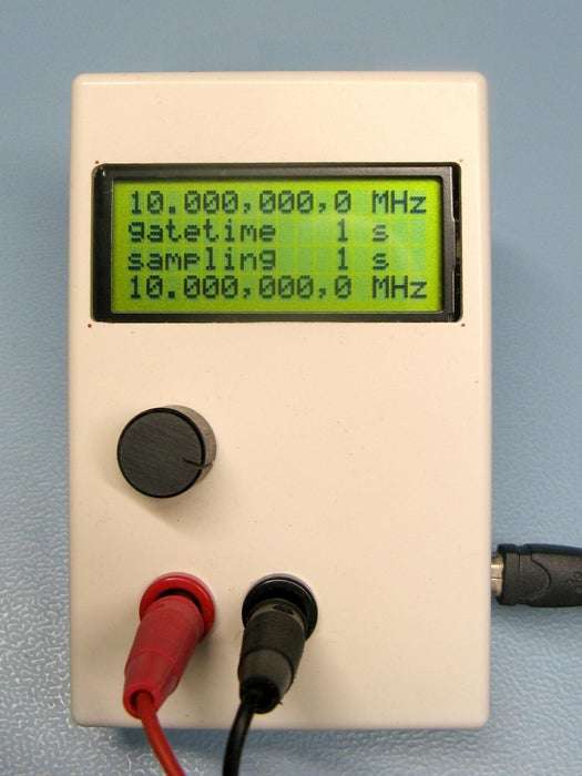
Frequency counter (reciprocal)
Gate time selectable from 0.1 second up to 60 seconds
Frequency range from 0.1 Hz up to 10 MHz (tested)
Input 3.3V and 5V safe
Uses a STM32F103C8 (Blue Pill) and 16×4 LCD
code is available on gitlab:
https://gitlab.com/WilkoL/frequency-counter-with-v…
Supplies:
STM32F103C8 (Blue Pill)
16 x 4 LCD screen (HD44780 compatible)
10 MHz OCXO
74HC74
74HC00
3.3V voltage regulator
rotary encoder with button
some resistors, capacitors and diodes
perfboard
project box
Step 1: Another Frequency Counter?
Not so long ago I made another reciprocal frequency counter with an ATTINY2313 that works quite well. But it has no option to change the gate time. Its gate time is approximately one second long, except when the input frequency is lower than 1 Hz when it lengthens the gate time to accomodate for a full cycle of the input frequency.
For most applications this is fine, the frequency I measure usually is stable and I just want to know as precisely as possible its value.But recently I started a project that asks for a frequency counter with a gate time of 32 seconds.
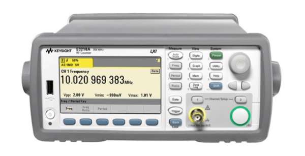
BTW, I wish I could afford the counter in the picture 🙂
Step 2: 32768 Hz
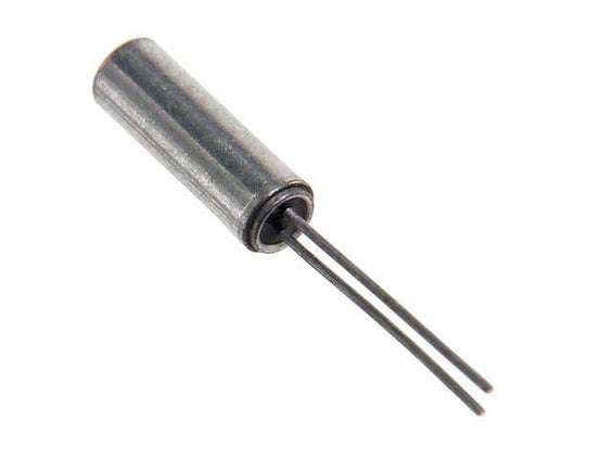
That new project is very low power, with a STM32L052K6 microcontroller that uses a 32768 Hz crystal. These crystals are very common in clocks, watches and other places where they are used for time keeping. Crystals are dependable, stable and precise, except for one thing, their frequency varies (a little) versus temperature. To keep the frequency stable at all temperatures there are several options.
One is to put the crytals in a temperature controlled environment, in this frequency counter that is done with an OCXO, an Oven Controlled Xtal Oscillator. But an oven uses a lot of power so that is not an option for my low power project.
A second option is to use a TCXO, a Temperature Compensated Xtal Oscillator. One very popular example of that is the DS3231 from Maxim. It is extremely accurate and low power as well. But this would add an extra integrated circuit to my project and the means more pcb space, cost and power.
But there is a third option. The STM32L052K6 has a Real Time Clock with a special function. It uses an ordinary 32768 Hz crystal so it is clocked with 32768 pulses per second. but when the frequency isn’t exactly 32768 Hz, it can add or subtract pulses to compensate.
Step 3: A Correcting Real-Time-Clock
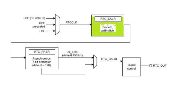
Of course the microcontroller does not “know” when the frequency isn’t exactly right, that has to be measured with a frequency counter first. One can then tell the RTC to add or subtract the right number of pulses to come to exact 32768 pulses per second.
Inside the STM32L052 there is also a temperature sensor which we can use to make adjustments of the frequency at different temperatures.
Those adjustment happen over a time period of 32 seconds. So in this 32 second period the RTC will add or subtract pulses to come to a total of 1048576 pulses. The number of extra or less pulses needed can vary and they are spread out of those 32 seconds, and therefore one second can be a little longer or shorter than the next second, still, over the 32 second period they will average out to exactly 1 second.
Step 4: Reciprocal Frequency Counting
So I needed a frequency counter with a gate time of 32 seconds. If I was going to make one to do that, I might as well make one with several gate times. I made it with gates times going from 100 ms in steps of 100ms up to 1 second, then from 1 second up to 50 seconds and a bonus of 60 seconds. Longer gates times are possible, but not without some changes, later more about that.
The frequency counter uses the reciprocal method which means that it counts two signals at the same time, the input signal of course and a second high frequency signal. This second frequency should be as high a possible, the exact value of it isn’t very important although its value must be known as precisely as possible.
The trick is to start counting both signals at exactly the same time and also to stop at exacly the same time, both times at the rising edge of the input signal. This is done with a D-flipflop that triggers the start and end of the measuring at the rising edge of the input signal. This way we know that we have measured a whole number (integer) of cycles of the input signal.
At the same time we counted the other high frequency signal, not starting at the rising or falling edge of it, but as it is high frequency, missing one of two pulses does not change the total very much. With those two numbers the frequency of the input signal can be calculated with a very high precision.
For a longer explanation of the reciprocal measuring method take a look at my other counter project, here on instructables. https://www.instructables.com/High-Resolution-Freq…
Step 5: Schematic
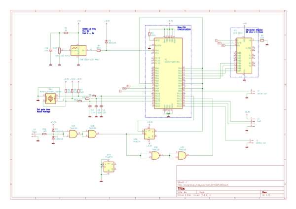
For this counter I used a STM32F103C8 (on a BluePill development board), a D-FlipFlop, a 10 MHz OCXO and a LCD screen with 4 lines of 16 characters. Unfortunately the backlight of the screen is broken, so I can’t use it without enough light.
As the OCXO uses a lot of power, esspecially when it is just switched on, I did not use battery power. It is powered with 5V coming in via a USB connector.
A 74HC00 (QUAD NAND) is used at the input and a very small delayline. A rotary encoder is used for setting the wanted gate time.
Step 6: Input
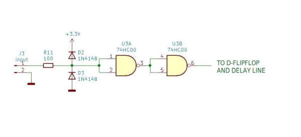
The input is as simple as it gets, a resistor and two diodes to protect the gates of the 74HC00, only one gate would be enough, but I needed just three in the whole schematic. So one was left, and I added it after the one on the input.
Step 7: Triggering With D-FlipFlop

The D-input of the D-FlipFlop for triggering section is set high by the microcontroller. This happens with the required gate time. Then, as soon as there is a rising edge on its clock input, the Q-output is set. That signal is send to the Channel-1 inputs of all 4 timers, the current value of those timers is recorded and processed. The timers never stop.
Because there is a small delay in the D-FlipFlop for the input signal to reach the output, I delayed the input frequency with two NANDs before it is send to the timer that counts the input frequency. That way both the capture-signal and input-signal arrive at the same time.
if (timeout)                                            //defines the approx gate-time
    {
        timeout--;
        wait_time = ((timeout - 1) / 1000) + 1;                //calc wait time so you know how long to
        if ((timeout % 1000) == 0) show_wait_time = 1;        //wait for the next measurement result
    }
    else
    {
        LL_GPIO_SetOutputPin(GPIOA, LL_GPIO_PIN_11);        //set D-flipflop HIGH
        show_wait_time = 1;
    }

Source: Frequency Counter With Variable Gate Time
- What is the selectable gate time range?
The gate time is selectable from 0.1 second up to 60 seconds. - How does the reciprocal counting method work?
It counts two signals simultaneously, starting and stopping both at the rising edge of the input signal to measure a whole number of cycles. - Can this circuit handle 5V inputs safely?
Yes, the input is designed to be safe for both 3.3V and 5V signals. - What is the tested frequency range?
The device operates within a frequency range from 0.1 Hz up to 10 MHz. - Which microcontroller is used for this project?
The project uses a STM32F103C8 (Blue Pill). - How are the start and stop signals triggered?
A D-flip-flop triggers the start and end of the measuring process at the rising edge of the input signal. - Why was a 10 MHz OCXO chosen over other oscillators?
An OCXO provides a stable high-frequency reference signal required for precise calculation, though it consumes significant power. - What component protects the 74HC00 gates at the input?
A resistor and two diodes are used to protect the gates of the 74HC00.