For our ECE 4760 final project, we designed and built a wireless computer pointing device with accelerometer based movement control. Our implementation allows the user to wear a set of hardware (a glove and connected armband) and control a cursor through different hand orientations and finger presses. Users can operate their computers with their hands in midair without the hassle of desks surfaces or wires.
This system connects to an computer using standard USB and supports Windows, Mac, and Linux operating systems.
High Level Design
Rationale and Inspiration
While brainstorming an idea for our final project, we decided to base our project idea around what we enjoy most about Electrical and Computer Engineering: computers. We felt that it would be interesting to somehow design a microcontroller based project which could somehow interface or communicate with our own personal computers. Additionally, we were originally inspired by a specific last project from the previous semester: a sign language translating sensor glove. This device was able to sense hand gestures and map them from a sign language alphabet to a standard English alphabet. With the thoughts of computer interfacing and hand motion in mind, we came up with this project idea.
The motivation for this project was to create an intuitive glove-based pointing device for multiple applications. The hope was to be able to create not just a working project but a fully-developed device in terms of intuitive functionality and practical, usable features. We note that past ECE 4760 project groups and outside hobbists have developed similar pointing devices, some glove-based and some not. While our end goals were similar to some previous projects, our intent was to only reference their projects as proof of the feasibility of our idea and ultimately to develop a more elegant, full solution to further the “glove mouse initiative”
Logical structure
At a high level, our design consists of two main parts: a glove and a base station. Operation of our device begins with the glove. A user wearing the glove can use hand tilt orientation and finger presses to operate the glove. The glove senses these user actions via two types of sensors: accelerometers and finger contact pads. After the glove’s microcontroller processes the input data, it forwards a message a transceiver mounted on the glove unit. The transceiver then transmits this message wireless to a transceiver on the base station. The receiving transceiver forwards the the message base station microcontroller. Finally, the microcontroller converts the message into a computer HID user friendly format and moves the computer cursor appropriately.
Hardware/Software tradeoffs
To interface our project with computers, we realized that we would be required to somehow implement a USB HID class device. During the planning stages of our design, we researched different ways implementing a USB HID and discovered that we could either proceed by doing this through software or hardware support. We came to the conclusion that our design would require an microcontroller in our base station in order to receive wireless messages and process the information. With this in mind, we decided it would be a more practical and simple to purchase a single hardware board that could perform both these functions. Almost too fittingly, we found a board that could perform the functions we needed and provided relevant example libraries, all within our budget. Additionally, we took into account the short time span we had for this project, and believed it’d be more effective to focus on developing our design than getting caught up in the details and semantics of the USB HID class.
Standards
Our design requires a computer to recognize our device as a human interface device, and thus our design must abide by USB HID specifications. This is implemented in the referenced USB mouse library used with our Teensy++ 2.0 microcontroller. Our design also features low powered radio transceivers using frequency-hopping spread spectrum. To follow FCC regulations, we use an FCC approved set of transceivers (this is detailed more below in Legal Considerations).
Hardware Design and Implementation
Hardware Overview
As mentioned above, the physical design of our project includes two main parts: a glove unit and a base station. The glove unit’s main purpose is to process information from sensors and transmit the user input to the base station. The base station’s purpose is to receive the glove’s sent data and forward it to the user’s computer in a HID class friendly format. Each unit has its own unique microcontroller and respective peripherals, which are detailed more below.
Glove Unit
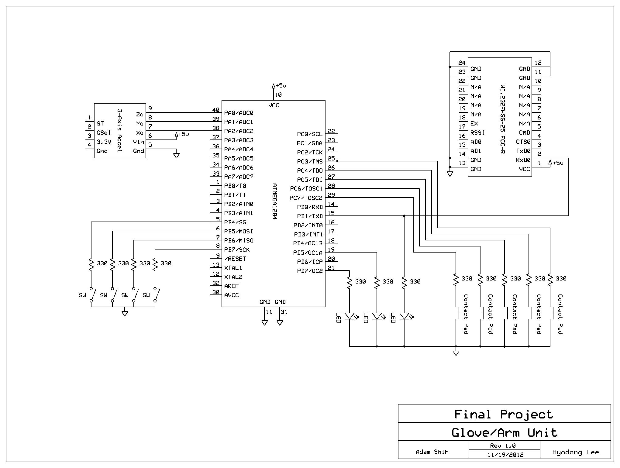
The Glove Unit is the set of hardware that the user physically wears during operation of the Glove Mouse. It carries a Atmega1284 microcontroller mounted onto a custom PCB designed by Bruce Land. Connected to the glove’s microcontroller are 5 contact pads, a 3-axis accelerometer, a wireless transiever, 3 different colored LEDs, and a 4 pins of a 8-pin DIP switch.
The user of the Glove Mouse has two primary modes of input as well as one auxiliary mode. The primary modes of input are hand orientation for mouse movement control and buttons for mouse clicks and control over movement enabling. Hand orientation is sensed by the 3-axis accelerometer in terms of tilt, and outputs an analog voltage to pin A.0, A.1, and A.2 of the glove MCU. These pins are connected to the Atmega1284’s internal analog-to-digital convertors, and are converted to a char value between -128 and 127. Button presses are sensed by contact pads placed on the sides and pads of the glove’s fingers. The contact pads are connected to pins C.3 through C.7 on one side and MCU ground. Each pad simply shorts the microcontroller’s input pin (originally pulled high via software) to ground. Contact pads are wired in series with a 330 Ohm resistor to protect respective microcontroller ports. Similarly, 4 DIP switches are wired from ground in series with a 330 Ohm resistor to MCU pins B.4 through B.7 to control mouse user preference features such as sensitivity, axis inversion, and rapid fire clicking.
In terms of outputs, the Glove Unit’s MCU is connected to the input of the of a wireless transceiver. Specifically, it connected to port D.1, the first of two USART channels supported by the Atmega1284. This port is appropriately chosen to interface with the Radiotronix transceiver used, which communicates via USART. Additionally, the Glove Unit features 3 status LEDs, connected to port D.7, D.5, and D.1. Respectively, these LEDs provide information regarding power on, button clicks, and communication between MCU and transceiver.
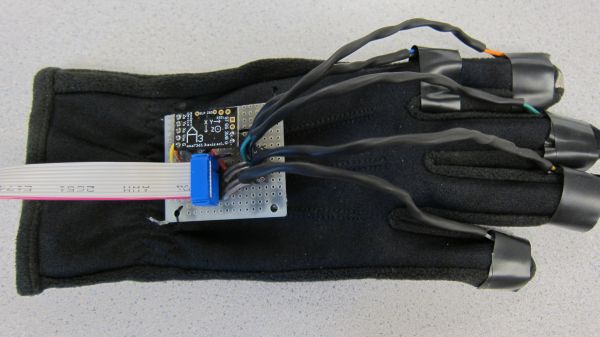
Close-up of glove solder board. This provides the detachable interface between the armband and glove’s sensor hardware
Physically, the Glove Unit was assembled as two separate pieces: a custom glove and a custom arm band. Together, these form the circuitry for the one functional module described above. We chose to separate this design into two pieces due to the size of our components and the limited space avalible on the glove. As a result, the glove actually only carries a small solder board that is connected to all the acclerometer and contact pads. The solder board is sowed onto the back-hand area of the glove. A 5×2 header to connected to this board in order to interface with the arm band, which carries the rest of the components/circuitry plus a 9V battery for power. A simple female-to-male flat-wire is used to connect the two pieces. This physical design and choice of mounting location on the user is chosen for wearbility, comfort, and hardware safety.
Accelerometer
In order to detect and map user hand motions to mouse cursor movement, we chose to use accelerometers to measure hand tilt and orientation. Specifically, we chose to use a Modern Device 3-Axis Accelerometer Module. This chip carries a Freescale MMA7361 three-axis analog accelerometer. The 3-Axis Accelerometer Module additionally features a low-dropout voltage regulator (Microchip MCP1700) to provide 3.3V power to the MMA7361 and 10nF capacitors on the outputs of the accelerometer to minimize clock noise. Because of this, we were able to use the accelerometer module straight out-of-the-box (connecting its power input to Vcc).
Contact Pads
We chose to use contact pads in order to detect pointing device button commands. Originally, we had decided to purchase small push buttons and install them on each of the glove’s finger pads. However, due to pricing, minimum order quantity, and size constraints, we could not find a feasible solution. As such, we determined that we could build soft contact pads from available lab materials. The contact pads we built have the same exact functionality and user interface as typical push buttons: each contact pad features two output wires that are shorted together when contact pad is pressed. Contact pads are connected to glove’s design via one lead to ground and the other to a 330Ohm resistor in series with the MCU’s input ports
Parts List:
| Part | Unit Cost | Vendor | Quantity | Total Cost |
| Custom PCB (designed by Bruce Land) | $4 | Lab Stock | 1 | $4 |
| Atmega 1284 | $5 | Lab Stock | 1 | $5 |
| Teensy++ 2.0 (w/ headers) | $27 | PRJC | 1 | $27 |
| Radiotronix WI.232FHSS-25-FCC-R Transceivers | $0 | Donated by Bruce Land | 2 | $0 |
| Modern Device 3-Axis Accelerometer Module | $10.95 | Modern Device | 1 | $10.95 |
| Contact pads | $0 | Built from lab materials | 5 | $0 |
| Isotoner Smart Touch glove | $4 | Walmart | 1 | $4 |
| Solder board | $2.50 | Lab stock | 4 | $10.00 |
| 40-pin DIP socket | $0.50 | Lab stock | 2 | $1 |
| Header pins/plugs | $0.05 | Lab stock | 147 | $7.35 |
| SIP Sockets | $0.05 | Lab stock | 10 | $0.50 |
| DIP switch | $0 | Lab stock | 1 | $0 |
| Flat cable | $2 | Lab stock | 1 | $2 |
| LEDs | $0 | Lab stock | 5 | $0 |
| Screws | $0 | Lab stock | 3 | $0 |
| 9V battery | $2 | Walmart | 1 | $2 |
| Laser diode | $0 | Lab stock | 1 | $0 |
| Velcro (30″) | $3.79 | Michaels | 1 | $3.79 |
| ESD Foam | $0 | Lab stock | 1 | $0 |
| Wire | $0 | Lab Stock | 10′ | $0 |
| Resistors | $0 | Lab Stock | 14 | $0 |
| Total Cost | $77.59 |
For more detail: Glove Mouse Using Atmega1284