I. Introduction
Simply write; your computer will undersand!
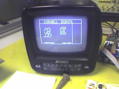
We have designed and implemented a Handwriting Recognition System using a touch screen from a Palm Pilot m125, a black and white TV and a Mega32 microcontroller.
Unfortunately, due to the lack of specifications regarding the built-in LCD on the Palm Pilot, we were unable to reverse engineer the LCD protocol. We were, however, able to understand how the touch screen works after some careful investigations.
This project is highly adaptive. With sophisticated algorithm, it should be able detect any patterns. In our project, however, we choose to use a simple algorithm, Nearest Neighborhood Algorithm, as we have very limited amount of time. Thus far it can only recognize simple characters but it is easily extensible. There is no fundamental difference between recognizing a character and any other kind of patterns using our algorithm.
II. High Level Design
Source and Rationale of the Project
Initially we started Automatic Speech Recognition. After a few days of careful considerations, however, we decided that lab is a horrible environment for voice recording and that Mega32 is too slow for full-fledged Fast Fourier Transform algorithm. We came across Palm-PPP, a project from last year when we were looking for new ideas. It is a Simon game based on a Palm m125 touch screen. We thought it would be fantastic idea to do handwriting recognition like Graffti. It requires a touch screen, a novel hardware input device and some smart programming, a perfect combination for a final project.
Theory of Operations and Background Math
There are essential two three parts to this project, data acquisition via touch screen, Recognition Algorithm and Video Generation.
-
1. Data Acquisition
After reading through the Palm-PPP project, we realized that touch screen was not that hard to use. The device driver, therefore, should be an easy thing to write.However, it is not the case as they stated. As mentioned in Palm-PPP project, the touch screen has four pins, each connected to top, right, bottom, and left side of the screen. It is also correctly stated as a purely analog device that detects position by varying resistance between two pairs of pins (top and bottom, left and right). They claim that the touch screen has very low resolution (and it is not even linear).
We determined early on that the touch screens analog output did not have a high enough resolution or linear relationship to obtain precise and intricate motions.
Their game therefore divides the screen to only four blocks, four giant pixels essentially. They only need to detect which of the four blocks a stylus touches on. This is simply not true that you cant better motions beyond four giant pixels as I have used Palm m125 to stretch arbitrary curves and it works pretty works tracing my stylus movements. Either engineers at Palm use some really crazy non-linear interpolating algorithm to magically compensate the shortcomings of their touch screens or the touch screen must be linear and very easy to deal with. We prefer the later scenario. We also believe that linearity is a safe bet. There must be something that they have done wrong.
Initially, the four pins behaviors are described as bizarre at best. For one setting, moving in direction, the voltages at different pins will change simultaneously. There seem not to be any independence between pins corresponding to any direction. In some random scenario, two pins will behave in exactly the same way, able to detect movement in, say, X direction, while any Y direction movement is completely ignored. We swap the pin settings for detecting X position and were only overjoyed to find that we were able to isolate Y position as well. We realize that it is possible to isolate the movement in one direction, or another, but not both.
Careful investigation of various settings that give us isolated readings of X, Y positions reveals that the touch screen is actually a very simple device that behaves exactly like a potentiometer with a little twist, that it has four pins instead of the usual three. As it turns out, it is essential that it has four pins. You can imagine that with Top connected to Vcc and Bottom connected to GND, left and right can be read as the inputs for Y positions. The voltages at both pins will vary at the same time and be of equal magnitude. When reading X, we need to connect Left to Vcc and Right to GND, TOP and BOT then can serve as inputs.
We also use a pair of amplifier and RC filter with a cutoff of 11Hz to filter out digital noises for each input. This will be discussed in the hardware section.
2. Background Math
There are a lot of choices concerning the algorithm we can use to recognize patterns. Recognition algorithms fall under two categories. We can track the motions of the stylus for feature extraction for each pattern; or we can record positions for feature extraction. We choose the latter since the former will involve a lot more complicated implementations at the software level and will surely require more computational power as offered by our microcontroller.
The mathematical fundamentals for our Nearest Neighbor algorithm are very simple. Imagine our bit map of each pattern lives in N-dimensional space. Each pattern is a vector in that space. We will take 3d space as an example.
As you can see, character A is the red vector in our 3d space; B is the yellow vector and W the green. It is reasonable to expect that A is closer than B than it is to W because A appears more similar to B than it is to W. Let A, the brown vector, be the pattern rewritten by someone else using a stylus on a touch screen. It is closer to A than any other vector, supposedly.
To see how close one vector is to another, we need to find the dot product between two vectors. This would give us information on the angle between two vectors. It is also very easy to do dot product between two vectors. It naturally brings us to the question on how we vectorize each character. This will be explained in the software section.
Hardware/software tradeoffs
There are no hardware and software tradeoffs in our project because we do not have sections of the project where hardware can be substituted by software or vice versa. For example, to have exact timing, as required by video generation, we have to use hardware interrupt instead of any other kind of software timing scheme.
Except for NTSC standard used in video generation, whose code was provided by Professor Bruce Land, we do not use any standards known to us. The touch screen torn from Palm m125 is only a simple analog device that we believe does not implement any sort of standard. We also do not believe that we violate any patent laws since all the technologies and products we used are strict on public domain.
III. Hardware Design
There are five hardware components. They are Touch screen, Op-amplifier and RC filter, Mega32 Microcontroller, Digital and Analog converter and TV. They are connected exactly in this order Touch screen->Op-amplifier and RC filter->Mega32 Microcontroller->Digital and Analog converter -> TV.
There are only four pins on the touch screen. They are connected to Op-amps and Mega32 as shown by the table below.
|
PINS |
Connections |
|
Left |
A.1(after going through filter-amplifer pair) and C.1 |
|
Top |
A.5(after going through filter-amplifer pair) and C.3 |
|
Right |
C.5 |
|
Bottom |
C.7 |
Table 1 shows the connections between the touch screen and Mega32. Notice that PORT A is our Analog to Digital conversion ports and that Left and Top are inputs to Mega32 and they have to be filtered and amplified through our filter and amplifier pair before connecting to A.1 and A.5. Figure 6 shows two pairs of filter-amplifiers.
Our filter is simple RC filter with R = 30k��, C = .47��F and a cutoff of 11Hz. Our Op-amp is a standard Op-amp gain of 3.
PORTD is our standard output for video signals. Video generation is extensively documented. PORTD.5 and 6 are connected to a resistive DAC as follows
We then use the standard black and white TV provided in the lab to display our results. We could have used a graphical LCD or the LCD built into m125 but we don��t have a graphical LCD around the lab nor do we have specifications regarding the LCD therefore we choose to use our bread and butter black and white TV, which is also the cheapest option.
IV. Software Design
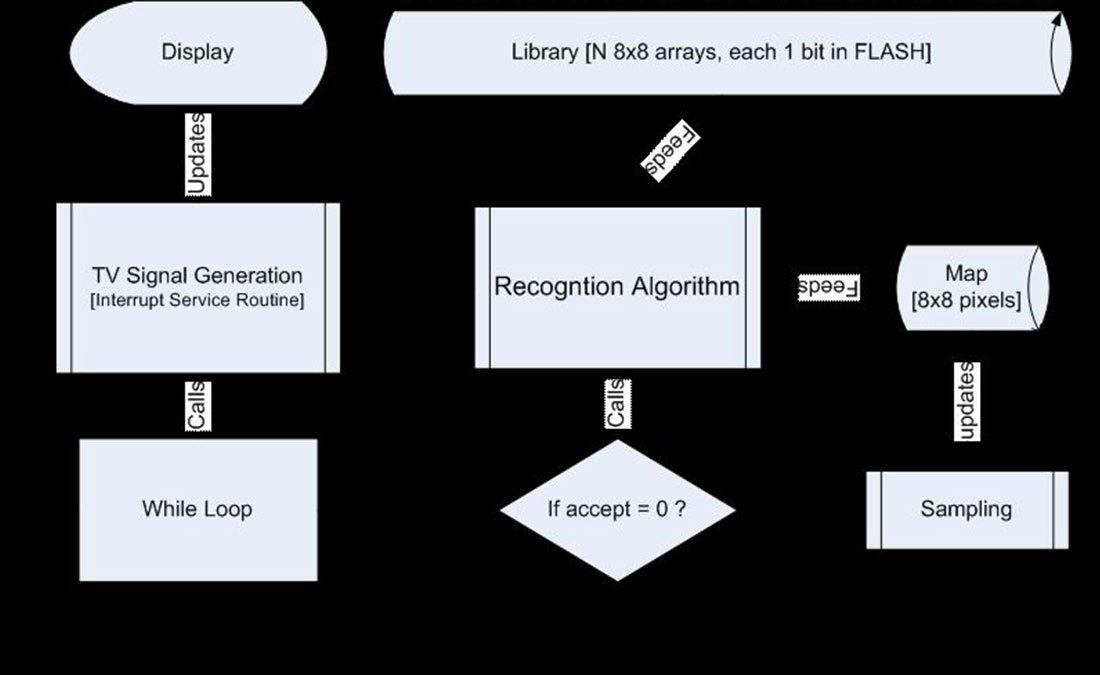
Figure 5 is reproduced here for software section because it exactly demonstrates how software portion of this project works. Rectangles represent predefined routines; diamond represents control routine; cylinders represent data structures. As usual, we have an infinite loop as our starting point. As the program executes each loop, it generates one frame with TV Signal Generation Interrupt, provided by Professor Land. During each loop, a control routine runs to see if we still need sampling or we should start recognize patterns. Sampling is always running as long as a flag, ACCEPT, is false. ACCEPT turns true when user tap on a predefined portion of the touch screen to signal the beginning of recognition. There are therefore, several important components of the code, TV signal generation, Sampling, Data Storage, Control, and of course recognition.
Sampling
|
PINS |
READ Y |
READ X |
||
|
Left |
Amp-filter -> PINA.1 set to A2D conversion |
C.1 set to INPUT MODE = high impedance |
Amp-filter -> PINA.1 set to Dont care |
C.1 set to OUTPUT mode = Vcc |
|
Top |
Amp-filter -> PINA.5 set to Don��t care |
C.3 set to OUTPUT MODE = GND |
Amp-filter -> PINA.5 set to A2D conversion |
C.3 set to INPUT MODE = high impedance |
|
Right |
C.5 = INPUT set to high impedance |
C.5 = OUTPUT set to GND |
||
|
Bottom |
C.7 = OUTPUT set to Vcc |
C.7 = INPUT set to high impedance |
||
Sampling is not exactly hard once we understand how the touch screen works. The function Sample() implements sampling and is called by while loop each frame. Notice that as we explained above, we can only independently either read X or Y but not both. Therefore, we need to switch inputs and outputs in order to get proper reading out of the touch screen. Table 2 specifies each modes for each port in each situation. Sampling divides the touch screen into a 40×40 bit map so digitally we can only represent any writing the screen with 40×40 = 1600 pixels, which is more than enough for our purpose. Sampling calls draw() to actually draw points on TV screen using vidieo_pt(), courtesy of Professor Land, which essentially put one pixel to the massive screen[] array one at a time. However, we can not possible store 40×40 = 1600 pts in our tiny memory, we chose to down sample each direction by a factor of 5, which reduces our resolution to that of 8×8 = 64. Sampling calls writeMap() function to do the down-sample and pixels are therefore stored in map[8], a one-byte array of size 8, with each bit representing each pixel.
Control() will clear the screen if sample() detects that a user taps on a clear command portion of the touch screen. Control() will turn on recognition routine if sample() detects that a user taps on a command portion of the touch screen. testChars() is the routine that performs recognition algorithm.
Recogniton Algorithm
The basic mathematical theory is explained in the High Level Design section of this report. writeMap() essentially vectorizes 40×40 bitmap into map[8], a one-dimensional array, which can be seen as a long string of zeros and ones if you serialize each byte of the array. testChars() will then go through each character in the library and uses testLine() to perform line by line dot product on each character. The results will be stored in rank[3], which specifies the results of dot product and letter[3], which stores the corresponding character ranked by their results. The following is a example of a vectorized letter E in a 21×21 array.
Things That Did Not Work:
Everything that we tried worked. There are extra features (described below in the Conclusion section) that we did not have time to implement.
Parts List:
|
Item # |
Part |
Manufacturer |
Part # |
Cost |
|
|
1 |
Palm m125 Touchscreen | Palm |
$10 |
Pre-owned | |
|
2 |
Palm m125 Stylus | Palm |
$0 |
Pre-owned | |
|
3 |
Mega 32 | Atmel |
$8 |
||
|
4 |
STK 500 | AVR |
$15 |
||
|
5 |
Dual Op Amp | Analog Devices | LM7111 |
$1 |
|
|
6 |
TV |
$5 |
|||
|
7 |
Resistors & Capacitors | N/A |
$0 |
FREE | |
|
8 |
Boards x 2 | N/A |
$12 |
||
|
TOTAL COST: |
$50 |
For more detail: Handwriting Recognition System Using Atmel mega32