A nifty organization called Seeds of Change here in Anchorage, Alaska has been helping young people get started in productive commerce. It operates a large vertical hydroponics grow system in a converted warehouse and offers employment to learn the business of plant care. They were interested in a IOT system to help automate their water control. This instructable is mainly to document my volunteer efforts to build an affordable and expandable microcontroller system to assist in their efforts.
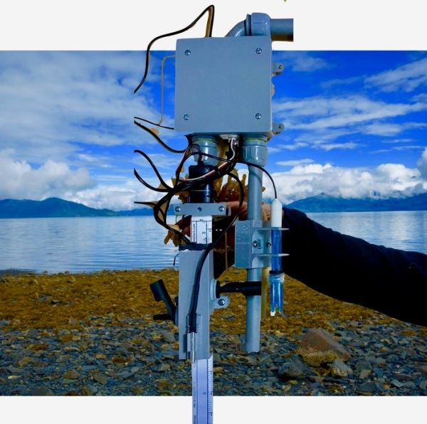
Large Hydroponic grow operations have come and gone over the last several years. The consolidation in this business has been marked by the difficulty in making it profitable. You have to automate like crazy by all accounts to make fancy bags of lettuce sell for a profit. These vertical units do not produce anything with any real calories–you are basically growing nicely packaged water–so you have to sell it at a premium. This water-resistant adjustable unit is built to control the water level in the main reservoir and constantly measure its depth, ph, temperature. The main unit runs on a ESP32 Featherwing and reports its findings through the web to a blynk app on your phone for monitoring and email or text warnings if things go wanky on you.
Step 1: Gather Your Materials
The design was based on cheap water-resistant electrical boxes from Lowes and a few holders that were 3D printed. The rest of the parts are all relatively cheap except for the pH unit from DF Robot and the ETape from Adafruit. DF Robot sells their new 3 volt version of their analog pH sensor with a cheaper pH probe and you will probably have to invest in a expensive version of this one for constant immersion. I did not include a conductivity tester yet but this will probably be in an upgrade after seeing how this one fares.
1. Two gang water-resistant electrical boxes from Lowes–with various fittings to hold straight and bent tubes-$10
2. 12″ Standard eTape Liquid Level Sensor with Plastic Casing Adafruit –$59 you can get this without the plastic housing for $20 less…
3. Adafruit HUZZAH32 – ESP32 Feather Board–great board.$20
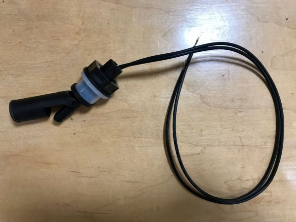
4. Aiskaer 2 Pieces Side mounted Aquarium Tank Side mounted Horizontal Liquid Float Switch Water Level $4
5. Adafruit Non-Latching Mini Relay FeatherWing
6. Lipo–battery $5 (power back up)
7. Couple LED’s various colors
8. Waterproof DS18B20 Digital temperature sensor + extras $10 Adafruit
9. Gravity: Analog pH Sensor/Meter Kit V2 DF Robot $39–Industrial pH probe will cost $49 more
10 Waterproof Rugged Metal On/Off Switch with Red LED Ring – 16mm Red On/Off $5
11 Plastic Water Solenoid Valve – 12V – 3/4″ (Don’t get the 1/2 inch–it doesn’t fit anything…)
12. Diymall 0.96″ Inch Yellow Blue I2c IIC Serial Oled LCD LED Module $5
Step 2: Wire It
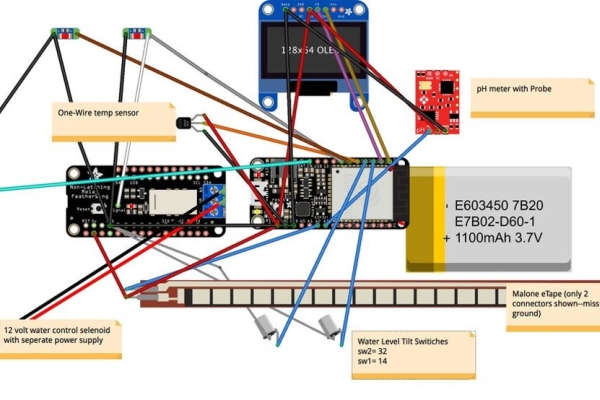
Just follow the Fritzing diagram for the wiring. The esp32 was mounted on a photo board with the OLED screen on the opposite side where it would face the small hole in the central back of the gang-box. The LED’s were connected to two digital outputs of the ESP. One is indicative of a WiFi connection and the other announces if the Relay is turned on to the water output. The Lipo battery is attached to the battery input on the board. All other boards (pH, relay, Etape, one-wire temp, OLED) are all powered from the 3 volts on the board. The on/off is connected to ground by the enable pin on the main board–the LED is powered by NO connection to power. The eTape is definitely something to examine carefully — on my board the power and ground were reversed (RED/BLACK) and this seems to be the case with others who have had this problem (do search on adafruits web site for this problem…) also the resistor included in the head should be measured carefully–it is not as published. The new DH Robot board works with 3V now and so works with the ESP32. Could not get A0 to work — doesn’t take inputs before Wifi connection so I used other analog inputs.
Step 3: Build It
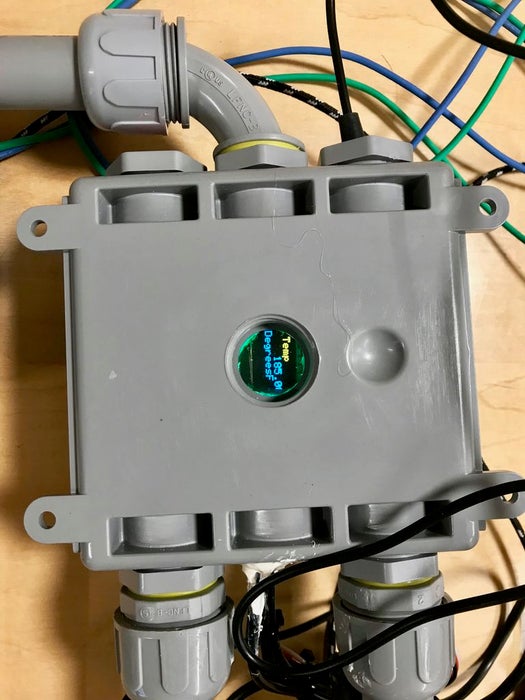
Everything fits rather neatly into the main box. Two poles of electrical conduit fit nicely out of the waterproof nipples at the bottom. These support the measuring instruments. They can be made arbitrarily longer or shorter to suspend the box higher or lower to the water level–your only limits are the length of your connecting wires that have to go into the box. These tubes should be sealed on the bottom with silicon. The instruments are suspended from 3D printed connectors that correspond to the curvature of the etape body and the conduit. They are easily adjustable with wing nuts. Special holders for the pH probe and the One-wire temp probe were also printed. The box support for the level – water- control switches was also 3D printed. These switches are waterproof and well designed and cheap. They appear to be enclosed reed switches. The box was filled with silicon after they were secured with included nut on the inside. The distance between these switches will determine how much fluid is allowed in before shutoff. All wires are lead through a lower opening and then sealed with silicon. The pH probe wire was fed in through the upper opening as it will most likely be changed out frequently. The on/off switch was hot glued into position. A rack to securely mount the esp32 with screen was 3D printed. A tiny round plastic window was siliconed over the back cover opening to protect the OLED screen from water.
Source: Hydroponics Controller