Summary of How to Interface an External EEPROM with AVR Atmega32
This article details interfacing an AT24C16A external EEPROM with an AVR Atmega32 microcontroller using the I2C protocol to store user configurations persistently. It covers hardware wiring, specifically grounding the write-protect pin and connecting SDA/SCL lines. The tutorial explains configuring TWI registers (TWBR, TWSR, TWCR) and provides C code functions for initialization, sending start/stop signals, writing data, and reading data from the memory chip.
Parts used in Interfacing External EEPROM with AVR Atmega32:
- AVR Atmega32 Microcontroller
- AT24C16A External EEPROM
- Green LED
- PCB (Printed Circuit Board)
In this article, we will explain how to communicate to an external EEPROM from the AVR Atmega32 MCU using the I2C communication protocol. So let’s begin our tutorial on how to interface an EEPROM (AT24C16A) with AVR Atmega32.
You will usually need an external EEPROM when your system has a certain set of user configurable settings that you need to save even when the system is powered off; so that the system starts with these configurations the next time it is powered on.
In this case, using an external EEPROM gives you the advantage of having a larger storage space (than the internal EEPROM inbuilt in Atmega32) in addition to keeping the user configurations safe from being lost even if the MCU fails.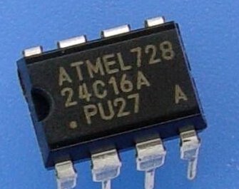 In this article, we will use the Atmel EEPROM AT24C16A. It is a 16K bit memory organized as 2048 word of 8 bits each (2048 Byte).
A0, A1 and A2 pins should be left unconnected for this specific EEPROM.The below drawing shows how to connect its pins to the Atmega32 I2C pins. You must make sure that pin 7 (WP is connected to ground) as this pin is a hardware write protection which won’t allow any writing operation to the memory unless it is grounded.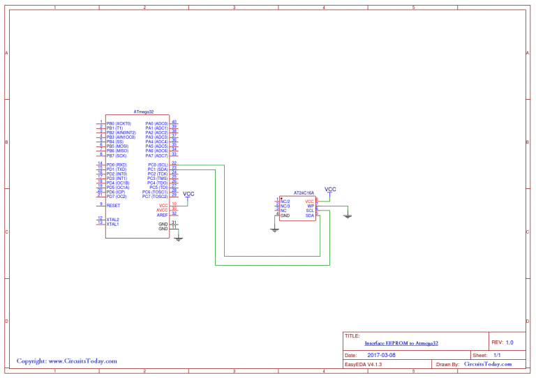
I2C Communication Protocol
I2C is a bus interface connection incorporated into many devices such as sensors, RTC (Real Time Clocks), and EEPROM. It is also referred to as Two-Wire Serial Interface (TWI) and it is ideal for communication between low-speed devices for a reliable communication over a short distance. The I2C protocol uses only 2 pins, one for clock (SCL) and one for Data (SDA). In Atmega32, these pins are pin22 (SCL) and pin23 (SDA). They are multiplexed over the I/O port C pins 0 and 1 respectively.
So, we will first configure and start the I2C protocol with the AVR microcontroller, and then we shall learn how to communicate with the EEPROM.
The configuration of I2C on AVR Atmega32:
In order to activate the I2C protocol, In master mode, on Atmega32, you need to configure 3 registers: TWBR, TWSR and TWCR. We shall use the TWCR register again (at a later stage in this tutorial) to operate the communication.
TWBR: TWI Bit Rate Register:
| R/W | R/W | R/W | R/W | R/W | R/W | R/W | R/W |
| TWBR7 | TWBR6 | TWBR5 | TWBR4 | TWBR3 | TWBR2 | TWBR1 | TWBR0 |
This is a 7-bit register whose value is used to determine the bit rate by which data will be exchanged between the two communicating devices. The equation used to calculate this bit rate is as below
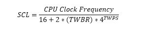
Where (TWBR) is the value in the TWI Bit Rate Register and TWPS is the value of the 2 bits (TWPS0) & (TWPS1) in the TWSR register which will be explained next.
For the purpose of this exercise, we will put the value 0x07 in the TWBR register.
TWSR: TWI Status Register:
| R | R | R | R | R | R | R/W | R/W |
| TWS7 | TWS6 | TWS5 | TWS4 | TWS3 | – | TWPS1 | TWPS0 |
In this register, we only need to configure bits (TWPS0 & TWPS1) which are used to determine the bit rate as detailed above. The value of TWPS in the above equation is determined as below
| TWPS1 | TWPS0 | TWPS |
| 0 | 0 | 0 |
| 0 | 1 | 1 |
| 1 | 0 | 2 |
| 1 | 1 | 3 |
In this article example, we shall clear these 2 bits to Zero.
TWCR: TWI Control Register:
| R/W | R/W | R/W | R/W | R | R/W | 1 | R/W |
| TWINT | TWEA | TWSTA | TWSTO | TWWC | TWEN | – | TWIE |
This 7-bit register is used to control the operation of the TWI. For now, we only need to set the TWEN bit (bit2), which enables the I2C module and overwrites the I/O functionality of its pins (Port C pins 0 and 1).
Having completed so far we can now write a function for I2C initialization as below:
void TWI_Init (void)

{       TWSR=0;

       TWBR=0x07;

       TWCR|=(1<<TWEN);}
I2C Operation
In order to start communicating using I2C you need to go through the steps given below:
- Taking control of the TWI bus, by sending a start signal to it when it is free.
- Start TWI Data Transmission
- Receive TWI Data.
- Stop transmission and Release the TWI bus.
We shall explain these steps in detail below.
-
Taking control of the TWI bus by sending a start signal to it when it is free:
For the MCU to be a master on the TWI bus and take control of it, the MCU senses the bus until it is free, and then sends a Start signal. Having done so the MCU seizes the bus and no other device can send data until the MCU releases the bus, to avoid data collisions. After that, the MCU can start sending data.
In this section, we will write a function for the MCU to be a master on the two-wire serial bus.
- Set the TWEN bit in the TWCR register to ensure I2C is enabled.
- Write 1 to the TWINT bit in the TWCR register to clear the interrupt flag.
This bit is set to 1 by the hardware when the I2C module finishes its current job and is ready to get more commands from the SW. Also clearing this bit starts the I2C module immediately. So every time we want to start the I2C module, we must ensure clearing this bit first and we shall poll till it becomes 1 again because this indicates the I2C has successfully executed the task.
Note: that this bit is never cleared by the MCU Hardware, you must clear it by Software. - Write 1 to the TWSTA bit in the TWCR register.
Setting this bit makes the MCU send a start signal on the bus when it is free, to declare that MCU is currently controlling the bus and will start transmitting data. - Poll the TWINT bit (previously cleared) until it becomes 1. Once this bit is set, it means that the MCU has successfully taken control of the bus as a master.
*To poll a bit: is to start an infinite loop that exits only when the bit’s value changes to the value we want. This is demonstrated in the code below.
#define get_bit(reg,bitnum) ((reg & (1<<bitnum))>>bitnum) // get bit macro used to get the value of a certain bit.

void TWI_Start (void)

{       TWCR= (1<<TWINT)|(1<<TWSTA)|(1<<TWEN);

       while (get_bit(TWCR,TWINT)==0) // this is polling on TWINT=0

       {       }

}
2. Start TWI Data Transmission:
After taking control of the bus, the MCU can send information to it. This is achieved through the steps below:
- Put the data you need to send in the TWI Data Register.
- Write 1 to the TWEN bit in the TWCR register to ensure I2C is enabled.
- Write 1 to the TWINT bit in the TWCR register to ensure it is cleared.
- Poll the TWINT bit (previously cleared) until it becomes 1. Once this bit is set, it means that the transmission is complete.
And here is the function code:
void TWI_Write (char data)

{

       TWDR=data;

       TWCR= (1<<TWINT)|(1<<TWEN);

       while (get_bit(TWCR,TWINT)==0)

       {       }

}
3. Receive TWI Data:
Receiving TWI data is even easier than transmitting. You need to follow these steps:
- Write 1 to the TWEN bit in the TWCR register to ensure I2C is enabled.
- Write 1 to the TWINT bit in the TWCR register to ensure it is cleared.
- Poll the TWINT bit until it becomes 1.
- Read data from the TWDR register.
This function is coded as given below:
void TWI_Read_Nack (char* ptr) // The function argument is a pointer to a memory place in the MCU to store the received data in

{

       TWCR=(1<<TWINT)|(1<<TWEN);

       while (get_bit(TWCR,TWINT)==0)

       {       }

       *ptr=TWDR;

}
4. Stop transmission and Release the TWI bus:
Once you finish data transmission, you should release the bus so that other devices can use it. This is achieved through the following steps:
- Write 1 to the TWEN bit in the TWCR register to ensure I2C is enabled.
- Write 1 to the TWINT bit in the TWCR register to ensure it is cleared.
- Write 1 to the TWSTO bit in the TWCR register to send a stop signal and release the bus.
This is coded as given below:
void TWI_Stop (void)

{

       TWCR=(1<<TWSTO)|(1<<TWEN)|(1<<TWINT);

}
EEPROM
Now we have seen all the necessary functions to start and operate the I2C on Atmega32, let’s see how we will use that with the EEPROM.
EEPROM Write Data
To write data to the EEPROM you need to do the steps given below with the MCU Software:
- Take control of the I2C bus.
- Send the slave address of the EEPROM. Which is constructed as below:
- The first 4 bits of the address are 1010
- The next 3 bits represent the memory page number.
- The last bit indicates whether the memory operation will be a read or write. (0 for Writing)
7 6 5 4 3 2 1 0 1 0 1 0 P2 P1 P0 Read/Write Indicator
- Send Start signal again
- Send the memory address to read from.
- Receive the data read from the EEPROM.
- Send stop signal to release the I2C bus.
This function can be coded as below:
void EEPROM_Read (char address, char* ptr) // the function arguments are an address in the EEPROM to read from and a pointer to a memory place in the MCU to store the read data in

{

       TWI_Start();

       TWI_Write(0xA8);

       TWI_Write(address);

       TWI_Start();

       TWI_Write(0xA9);

       TWI_Read_Nack(ptr);

       TWI_Stop();

}
Now, Let’s put all the pieces together!
The below program combines all the functions we wrote above and uses them to write a value to the EEPROM, retrieve it again, compare the retrieved data to the written one and light a green LED if they are equal (which should be the case).
#define F_CPU 8000000UL

#define get_bit(reg,bitnum) ((reg & (1<<bitnum))>>bitnum) // get bit macro used to get the value of a certain bit.

#include <avr/io.h>

#include <util/delay.h>


void TWI_Init (void);

void TWI_Start (void);

void TWI_Stop (void);

void TWI_Write (char data);

void TWI_Read_Nack (char* ptr);

void EEPROM_Write (char data, char address);

void EEPROM_Read (char address, char* ptr);


void TWI_Init (void)

{

       //set_bit(TWCR,6);

       TWSR=0;

       TWBR=0x07;

       TWCR|=(1<<TWEN);

}


void TWI_Start (void)

{

       TWCR= (1<<TWINT)|(1<<TWSTA)|(1<<TWEN);

       while (get_bit(TWCR,TWINT)==0)

       {

       }

}


void TWI_Stop (void)

{

       TWCR=(1<<TWSTO)|(1<<TWEN)|(1<<TWINT);

}


void TWI_Write (char data)

{

       TWDR=data;

       TWCR= (1<<TWINT)|(1<<TWEN);

       while (get_bit(TWCR,TWINT)==0)

       {

       }

}


void TWI_Read_Nack (char* ptr) // The function argument is a pointer to a memory place in the MCU to store the received data in

{

       TWCR=(1<<TWINT)|(1<<TWEN);

       while (get_bit(TWCR,TWINT)==0)

       {

       }

       *ptr=TWDR;

}


void EEPROM_Write (char data, char address)

{

       TWI_Start();

       TWI_Write(0xA8); //slave address is 1010.100 and a 0 in the 8th bit to indicate Writting.

       TWI_Write(address);

       TWI_Write(data);

       TWI_Stop();

}

void EEPROM_Read (char address, char* ptr) // the function arguments are an address in the EEPROM to read from and a pointer to a memory place in the MCU to store the read data in

{

       TWI_Start();

       TWI_Write(0xA8);

       TWI_Write(address);

       TWI_Start();

       TWI_Write(0xA9);

       TWI_Read_Nack(ptr);

       TWI_Stop();


}


int main(void)

{

       char R;

       DDRD=0b11111111;

       TWI_Init();

       while(1)

       {

              EEPROM_Write(0xE0,0x00);

              _delay_ms(1000); // You must allow suffcent delay for the EEPROM to complete the its internal write cycle

              EEPROM_Read(0x00,&R);

              if (R==0xE0)

              {

                     PORTD=0b01000000;

              }

       }

}
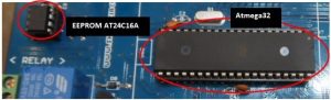
Photograph of the EEPROM and the ATmega32 connected (on a PCB)
Demo Video
For more detail: How to Interface an External EEPROM with AVR Atmega32
-
Why use an external EEPROM instead of internal memory?
External EEPROM offers larger storage space and keeps user configurations safe even if the MCU fails. -
How should the WP pin be connected on the AT24C16A?
Pin 7 (WP) must be connected to ground to disable hardware write protection. -
Which pins on the Atmega32 are used for I2C communication?
Pins 22 (SCL) and 23 (SDA) are used, which correspond to Port C pins 0 and 1. -
What is the purpose of the TWEN bit in the TWCR register?
Setting the TWEN bit enables the I2C module and overwrites the I/O functionality of its pins. -
How do you calculate the I2C bit rate?
The bit rate is calculated using the TWBR value and the TWPS bits found in the TWSR register. -
When should the TWINT bit be cleared?
The TWINT bit must be cleared by software before starting any new I2C operation or transmission. -
What delay is required after writing to the EEPROM?
A sufficient delay must be allowed for the EEPROM to complete its internal write cycle.