Summary of Week 11: Networking with ESP8266
This article details the creation of an ESP8266-based board displaying real-time MBTA bus arrival times on an LCD. The project involves designing custom Eagle libraries for the ESP8266 header and mounting the display. A voltage mismatch between the 5V ATmega32u4 and 3.3V ESP8266 logic levels is noted as a critical error discovered later in the process.
Parts used in the MBTA Bus Arrival Display:
- ESP8266 wifi module
- LCD display
- ATmega32u4 microcontroller
- Voltage regulator (for 3.3V power)
- Voltage divider circuit
- Eagle design software tools
- MA04-2 4x2 header
For this week I set out to make a board that will show realtime MBTA bus arrival times using the ESP8266 wifi module and a LCD. Seemed doable. People of the internet have been excited about the ESP8266 lately. Here is a snapshot of google trends for searches for esp8266 vs couple of other arduino favorite processors.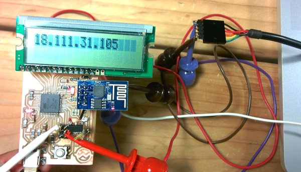
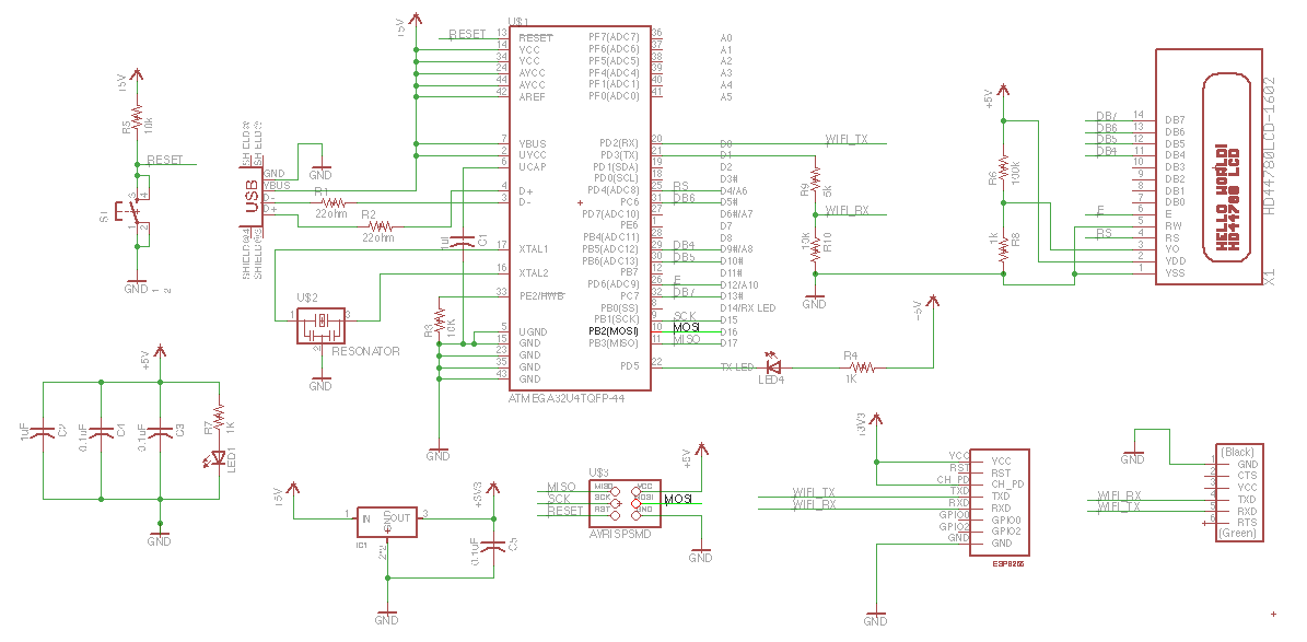
That’s the rough plan. I run the atmega32u4 and the LCD at 5V. The ESP8266 I power at 3.3V using a regulator. As for the logic chatter, I feed the 3.3V output of the ESP8266 to the atmega and I feed the output of the atmega through a voltage divider to bring it to 3.3V suitable for the ESP8266. This turned out to be a mistake that I will discover 15 hours later.
Mounting the lcd
I got a package from adafruits.com that I am modifying. First copy the package by
- opening target library
- selecting the device in the main window nav tree
- right-click copy to library
To get the mill to drill holes where needed, I am using the circle tool to draw filled cirlces (width 0).
ESP8266 package
I am making an eagle package and device for esp8266 header.
Steps:
- copy over a suitable part from another library (MA04-2 from con-lsb, a 4×2 header)
- open my library
- right click on part from source library
- click copy to library
- rename the package with
rename MA04-2.pac ESP8266_HDR_REVin the command bar - click package and select the package to edit
- get rid of all the crap that’s there (outline etc)
- add circles in the milling layer
- use name tool to give names (GND, RST, GPIO2, etc.)
- added some helpful text in the document layer
- create a new symbol (ESP8266)
- use pin tool to lay down 8 pins in row
- use name tool to add the same names I used in the package step
- create new device (ESP8266) (click device, pick a new name)
- use the place tool (plug thingie) to add the newly created symbol
- click new on the lower right to add the package
- click connect and go through and connect all the pins with all the pads
For more detail: Week 11: Networking with ESP8266
- What is the main goal of this project?
The goal is to make a board that shows realtime MBTA bus arrival times using the ESP8266 wifi module and a LCD. - How are the voltage levels managed between components?
The ATmega32u4 runs at 5V while the ESP8266 is powered at 3.3V, requiring a voltage divider for logic signals from the ATmega to the ESP8266. - What mistake was made regarding the logic chatter?
The author fed the output of the ATmega through a voltage divider to bring it to 3.3V for the ESP8266, which turned out to be a mistake. - Where did the author get the package being modified?
The author received a package from adafruits.com that is being modified for this project. - How were holes drawn for the milling machine?
The circle tool was used to draw filled circles with a width of 0 to get the mill to drill holes where needed. - What steps are taken to create the ESP8266 symbol?
The pin tool is used to lay down 8 pins in a row, and the name tool adds the same names used in the package step. - Which specific header part was copied for the new design?
A suitable part MA04-2 from con-lsb, which is a 4x2 header, was copied over. - Can I find more details about the networking aspect online?
Yes, more detail is available under the title Week 11: Networking with ESP8266.