Summary of Interfacing LCD 16×2 with ATMEGA32 AVR Microcontroller in 4-bit mode
This article details a project to interface a 16x2 LCD with an Atmega32 microcontroller using 4-bit mode. It explains the LCD's pin configuration, internal layer structure, and electrical specifications. The text provides C code for initialization, command sending, character writing, and display clearing, along with a circuit diagram description.
Parts used in the Atmega32 LCD Interface Project:
- Atmega32 Microcontroller
- 16x2 LCD Module (Liquid Crystal Display)
- 7066 or equivalent built-in controller chip
- 5V Power Supply
- Circuit connections including Data Bus (PORTA) and Control Bus (PORTB)
- Indium Tin Oxide (ITO) layers within the LCD panel
- Polyimide coating layers
- Front and Rear Polarizers
- Backlight Anode and Cathode connections
I’ve devised an intriguing and straightforward method for interfacing an LCD with the Atmega32 microcontroller and programming it.
I’ve employed a 16×2 LCD module, where “LCD” stands for “liquid crystal display.” This type of electronic display module finds utility in a wide array of applications, including mobile phones, calculators, computers, TV sets, and more. These displays are particularly favored for their versatility, featuring multi-segment light-emitting diodes and seven segments. The primary advantages of using this module are its affordability, ease of programmability, support for animations, and the absence of limitations when it comes to displaying custom characters, special symbols, and even animations.
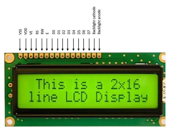
The display is equipped with a total of 16 pins, comprising 8 data pins (D0-D7) and 3 control pins (RS, RW, EN). The remaining 5 pins serve the purpose of supplying power and managing the backlight for the LCD. In 4-bit mode, data and commands are transmitted in a 4-bit format, with only 4 data pins (D4-D7) of the 16×2 LCD connected to the microcontroller.
The EN line, referred to as ‘Enable,’ functions as a control line responsible for signaling the LCD that the microcontroller has sent data to it or is prepared to receive data from the LCD.
The RS line, designated as ‘Register Select,’ is another control pin with a distinct role.
The third control pin is RW, denoting ‘Read/Write’ control. When RW is in a low state (0), it signifies that information on the data bus is being written to the LCD. Conversely, when RW is high (1), it indicates that the program is effectively querying the LCD.
VCC – connect to 5V
VSS – connect to ground
VEE – contrast adjustment
RS – register select 0:command, 1:data
RW – read/write 0:write 1:read
EN – Enable, falling edge trigged
D0-D7 – Data pins
A/LED+ – Back-light Anode(+)
K/LED- -Back-light Cathode(-)
Certainly, here’s a rephrased version:
This display module comprises 16 columns and 2 rows, resulting in a total of 32 characters. Each character is composed of 5×8 pixel dots. It operates at a voltage of 5.0V and has a current consumption of 1.6mA. The duty cycle is set at 1/16, and it incorporates a built-in controller, specifically the 7066 or an equivalent model. Its operational temperature range spans from 0°C to 50°C. While it is compatible with both 8-bit and 4-bit communication modes, it is employed in the 4-bit mode, which utilizes only four data lines. The adoption of 4-bit communication is an approach aimed at conserving the microcontroller’s pin resources.
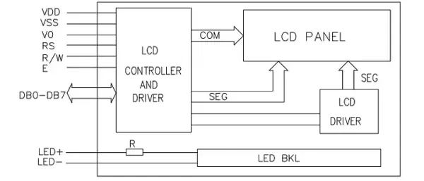
The internal circuit of the LCD
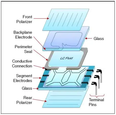
An LCD panel consists of multiple layers, and among these, the front polarizer is a critical component. This layer is responsible for manipulating the behavior of light rays in various directions, particularly causing them to vibrate in a single plane. The front polarizer is affixed to the outer surface of the upper glass piece, which also serves as a structural support for the LCD panel.
On the underside of this top glass layer, there is a transparent coating of Indium Tin Oxide (ITO), which is both conductive and forms the backplane or the common electrodes for the LCD panel. These electrode patterns, combined with the segment ITO, shape the display elements such as numbers, letters, symbols, and icons.
The orientation of the polyimide, a material applied to the bottom glass, differs from that on the top glass, creating a twist in the liquid crystal (LC) fluid. The next layer comprises a polyimide coating on the bottom glass, followed by the ITO segment electrodes. Finally, the rear polarizer is applied to the outer surface of the bottom glass. The polarization axis of this rear polarizer may align with the front polarizer or be shifted by 90 degrees, depending on the LCD panel’s chosen viewing mode.
Specifications of LCD Display
• Input Voltage – 5.0 V
• Supply Current – 1.0 mA (without backlight)
• Display format – 16*2 characters
• Duty Cycle – 1/16
• System Interface – 4 bit or 8 bit
• 5*8 dots include cursor
• Built – in – controller: ST 7066 (or equivalent)
• Operating Temperature 0-50℃
• Storage Temperature -10℃ − 60℃
Functions in LCD.h file
#ifndef LCD_H_
#define LCD_H_
#include <avr/io.h>
#define F_CPU 8000000UL
#include <util/delay.h>
#define LCD_CMD_CLEAR_DISPLAY 0x01
#define LCD_CMD_CURSOR_HOME 0x02
// Display control
#define LCD_CMD_DISPLAY_OFF 0x80
#define LCD_CMD_DISPLAY_NO_CURSOR 0x0c
#define LCD_CMD_DISPLAY_CURSOR_NO_BLINK 0x0E
#define LCD_CMD_DISPLAY_CURSOR_BLINK 0x0F
// Function set
#define LCD_CMD_4BIT_2ROW_5X7 0x28
#define LCD_CMD_8BIT_2ROW_5X7 0x38
//LCD DATA AND CONTROL PORTS
#define DATA_BUS PORTA
#define CTL_BUS PORTB
#define DATA_DDR DDRA
#define CTL_DDR DDRB
//LCD DATA PINS
#define LCD_D4 4
#define LCD_D5 5
#define LCD_D6 6
#define LCD_D7 7
// LCD CONTROL PINS
#define LCD_EN 3
#define LCD_RW 2
#define LCD_RS 1
//functions prototype
void lcd_init(void);
void lcd_send_command (uint8_t );
void lcd_write_character(uint8_t );
void lcd_write_word(uint8_t[]);
void lcd_clear(void);
void lcd_set_courser(uint8_t,uint8_t);
void lcd_goto_xy (uint8_t , uint8_t );
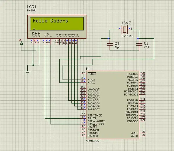
Circuit diagram
Atmel Studio C code
#include “lcd2.h”
/*
*Function name : lcd_init
*Parameters : void
*return : void
*purpose : initialize LCD pins as output
* and setting up the operation mode(4-bit)
* default setting (cursor on)
*/
void lcd_init(void)
{
DATA_DDR = (1<<LCD_D7) | (1<<LCD_D6) | (1<<LCD_D5)| (1<<LCD_D4);
CTL_DDR |= (1<<LCD_EN)|(1<<LCD_RW)|(1<<LCD_RS);
DATA_BUS = (0<<LCD_D7)|(0<<LCD_D6)|(1<<LCD_D5)|(0<<LCD_D4);
CTL_BUS|= (1<<LCD_EN)|(0<<LCD_RW)|(0<<LCD_RS);
_delay_ms(5);
CTL_BUS &=~(1<<LCD_EN);
_delay_ms(5);
lcd_send_command(LCD_CMD_4BIT_2ROW_5X7); /*2 line,5*7 matrix in 4-bit mode*/
_delay_ms(5);
lcd_send_command(LCD_CMD_DISPLAY_CURSOR_BLINK); /*Auto Increment cursor*/
_delay_ms(5);
lcd_send_command(0x80); /*display off*/
}
/*
*Function name : lcd_send_command
*Parameters: uint8_t command
*return: void
*purpose: sending a command to LCD by sending
* the first nibble then the second nibble
* enabling and disabling the LCD in between
*/
void lcd_send_command (uint8_t command)
{
DATA_BUS=((command&0b11110000)); /*Sending upper nibble*/
CTL_BUS &=~(1<<LCD_RS); /*RS=0, command reg*/
CTL_BUS |=(1<<LCD_EN); /*Enable pulse*/
_delay_ms(5);
CTL_BUS &=~(1<<LCD_EN);
_delay_ms(5);
DATA_BUS=((command&0b00001111)<<4); /*Sending lower nibble*/
CTL_BUS |=(1<<LCD_EN);
_delay_ms(5);
CTL_BUS &=~(1<<LCD_EN);
_delay_ms(5);
}
/*
*Function name : lcd_write_word
*Parameters : uint8_t word[20]
*return : void
*purpose : printing a full word to the
* LCD (Maximum 20 characters)
*/
void lcd_write_word(uint8_t word[20])
{
int i=0;
while(word[i]!=’\0′)
{
lcd_write_character(word[i]);
i++;
}
}
/*
*Function name : lcd_write_character
*Parameters: uint8_t character
*return: void
*purpose: sending one character to LCD by sending
* the first nibble first then the second nibble
* enabling and disabling the LCD in between
*/
void lcd_write_character(uint8_t character)
{
DATA_BUS=((character & 0b11110000));
CTL_BUS|=(1<<LCD_RS);
CTL_BUS |=(1<<LCD_EN);
_delay_ms(5);
CTL_BUS &=~(1<<LCD_EN);
_delay_ms(5);
DATA_BUS=((character & 0b00001111)<<4);
CTL_BUS |=(1<<LCD_EN);
_delay_ms(5);
CTL_BUS &=~(1<<LCD_EN);
_delay_ms(5);
}
/*
*Function name : lcd_clear
*Parameters : void
*return : void
*purpose : Clearing the LCD screen by sending
* the LCD_CMD_CLEAR_DISPLAY command to LCD
*/
void lcd_clear(void)
{
lcd_send_command(LCD_CMD_CLEAR_DISPLAY);
_delay_ms(5);
}
void lcd_goto_xy (uint8_t line,uint8_t pos) //line = 0 or 1
{
lcd_send_command((0x80|(line<<6))+pos);
_delay_us (50);
}
int main(void)
{
/* Replace with your application code */
lcd_init();
_delay_ms(20);
lcd_init();
_delay_ms(20);
lcd_write_word(“Hello Coders”); //Display “Not Registered”
_delay_us(20);
lcd_goto_xy(1,0);
lcd_clear();
_delay_ms(20);
}
Certainly, here’s a rephrased version:
lcd_init Function: The lcd_init function serves as the initialization routine for the LCD. It incorporates a 5ms power-on delay and transmits the 0x28 command to set up a 2-line 5×8 matrix with a 4-bit mode for a 16×2 LCD. Additionally, it issues the 0x0C command to enable display functionality. Following these steps, the LCD is now prepared to receive data for rendering.
lcd_send_command Function: Initially, the high nibble of the command is transmitted. Subsequently, the RS and RW pins are set low, and a high-to-low pulse is applied to the Enable (E) pin. Afterward, the lower nibble of the command is dispatched. At this stage, the command value can be forwarded to the LCD data port.
lcd_write_character Function: This function, when triggered with an enable pulse, causes the LCD to capture and present the data on a 5×8 matrix. RS serves as a data register in this context.
lcd_write_word Function: In this function, a string is taken as input, and characters are sent one by one to the LCD’s data port until the end of the string is reached. A while loop is employed to transmit each character in successive iterations, with a null character indicating the end of the string.
lcd_clear Function: When invoked, this function performs two essential actions: it clears the display and resets the cursor position to (0,0).
- What is the primary advantage of using 4-bit mode for this project?
Adopting 4-bit communication conserves the microcontroller's pin resources by utilizing only four data lines instead of eight. - How does the RW pin function when it is in a low state?
When the RW pin is low (0), it signifies that information on the data bus is being written to the LCD. - Can this LCD module support animations and custom characters?
Yes, the module supports animations and has no limitations regarding displaying custom characters and special symbols. - What voltage does the display module operate at?
The display operates at a voltage of 5.0V. - Which pins are used for data transmission in 4-bit mode?
In 4-bit mode, only the D4 through D7 pins of the 16x2 LCD are connected to the microcontroller. - What is the purpose of the RS line in this interface?
The RS line acts as Register Select, where a value of 0 indicates a command and a value of 1 indicates data. - How many total characters can the 16x2 LCD display?
The display comprises 16 columns and 2 rows, resulting in a total capacity of 32 characters. - What command is sent to clear the LCD screen?
The LCD_CMD_CLEAR_DISPLAY command (0x01) is sent to clear the LCD screen.