Summary of Interfacing PS2 Controller With AVR -Bit Bang
This article demonstrates interfacing a Sony PS2 controller with an AVR microcontroller using bit-banging instead of hardware SPI. It covers SPI basics, the PS2 protocol for analog mode configuration, and hardware wiring to an ATmega640. The provided code reads joystick values to control motor speeds, explaining the necessary software functions and byte sequences required to initialize the controller.
Parts used in the Interfacing PS2 Controller With AVR -Bit Bang:
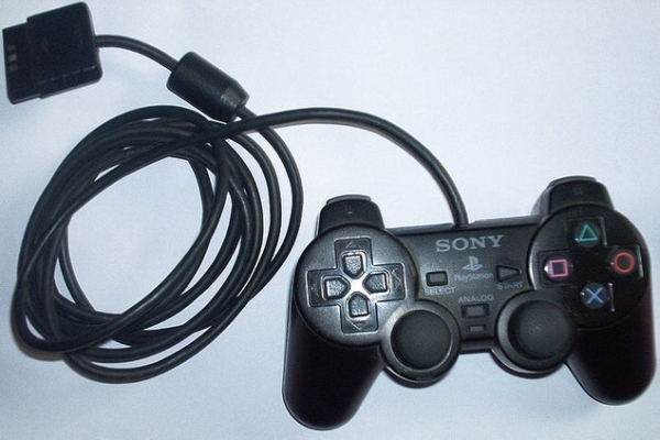
- Sony PS2 controller
- Atmega640 microcontroller
- AVRISP programmer
- One-to-one connector
- Winavr compiler
- progISP software
Hey friends in this instructable I will show you how to interface sony PS2 controller with AVR microcontroller .This will be your handy code which you can be used in future to control robots .You can get analogue value from joystick which can be used to control the speed of motor .
I have explained the code with help of 3 section
1)what is SPI ?
2)PS2 protocol
3)Finally the code
I have written the code for atmega640 in BIT BANGbut anyone who as worked with AVR can easily write a code for any series atmega microcontroller.You can also check ‘Interfacing PS2 with AVR -SPI ‘ in which i have used internal SPI of AVR.
Let’s get started!
Step 1: Material and Software Required
Materials required
1)sony PS2 controller
2)Atmega640
3)AVRISP programmer(or any other programmer depending upon your microcontroller )
4)one to one connector
software
1)Winavr(or any AVR compiler)
2)progISP
and of course you should have basic knowledge of AVR programming and embedded C.
Step 2: Understanding SPI
what is SPI ?
(you can skip this step if u know SPI communication )
Serial Peripheral Interface Bus or SPI bus is a synchronous serial data link de facto standard, that operates in full duplex mode. Devices communicate in master/slave mode where the master device initiates the data frame. Multiple slave devices are allowed with individual slave select (chip select) lines. Sometimes SPI is called a four-wire serial bus, contrasting with three-, two-, and one-wire serial buses. SPI is often referred to as SSI (Synchronous Serial Interface).
In SPI there are 6 connection
MOSI-master out slave in
MISO-master in slave out
SCK-clock is provided by master to slave by this pin
SS-slave select ,master selects a slave by this pin
VCC-voltage pin
GND -ground
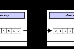
Both master and slave have shift register when master provides 8 clocks the content of each register is interchanged and data is transferred from master to slave and vice versa thus a full duplex communication .
so what is BIT BANG ?
Bit banging is a technique for serial communications using software instead of dedicated hardware. Software directly sets and samples the state of pins on the microcontroller, and is responsible for all parameters of the signal: timing, levels, synchronization, etc. In contrast to bit banging, dedicated hardware (such as a modem, UART, or SPI) handles these parameters and provides a (buffered) data interface in other systems, so software is not required to perform signal demodulation. Bit banging can be implemented at very low cost, and is used in, for example, embedded systems.
In this instructable I am using bit bang technique instead of using AVR’s SPI hardware .This code will work fine for many of our task .
you can refer this
1)http://avrbeginners.net/architecture/spi/spi.html
2)http://www.embedded.com/electronics-blogs/beginner-s-corner/4023908/Introduction-to-Serial-Peripheral-Interface
site to understand SPI further
Step 3: PS2 Protocol
This http://store.curiousinventor.com/guides/PS2/ best site to understand PS2 protocol.
Byte Sequence to Configure Controller for Analog Mode
— 0x43 Go into configuration mode
byte # 1 2 3 4 5
Command (hex) 01 43 00 0x01 00
Data (hex) FF 41 5A FF FF
section header digital
— 0x44 Turn on analog mode
byte # 1 2 3 4 5 6 7 8 9
Command (hex) 01 44 00 0x01 0x03 00 00 00 00
Data (hex) FF F3 5A 00 00 00 00 00 00
section header config parameters
— 0x43 Exit config mode
byte # 1 2 3 4 5 6 7 8 9
Command (hex) 01 43 00 0x00 5A 5A 5A 5A 5A
Data (hex) FF F3 5A 00 00 00 00 00 00
section header config parameters
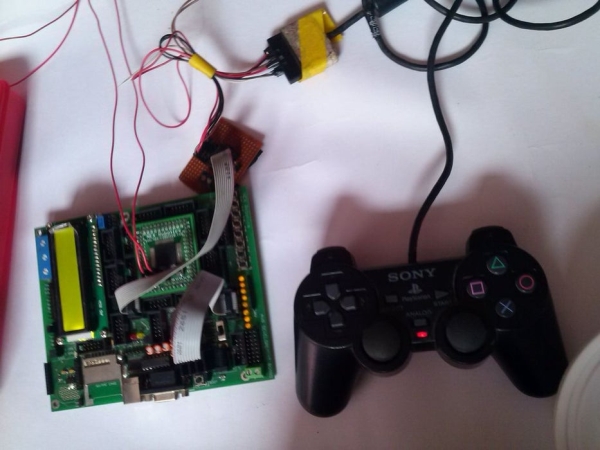
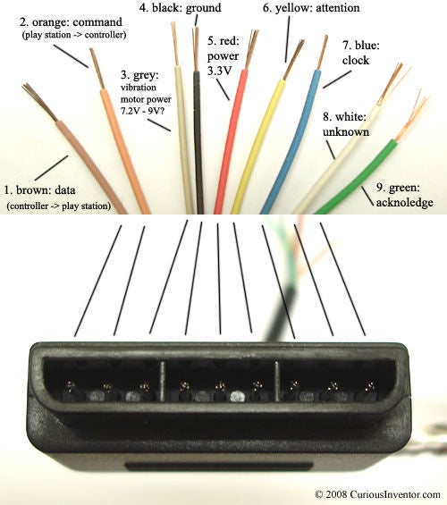
Step 4: Hardware Setup
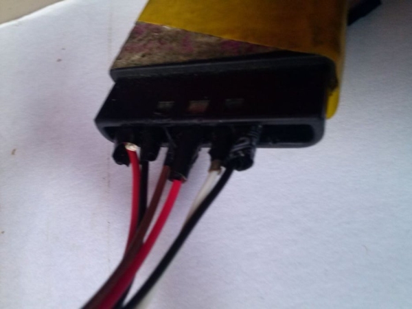
Setting a hardware is very easy you have to connect only 6 pins given below.you can use one to one connectors to connect PS2 side with board.Remove the plastic cover of one to one wire and make the gap bigger to fit in PS2 connector and then insulate the cnnector
————-LOOKING AT THE PLUG——————-
——————————-
PIN 1-> | o o o | o o o | o o o |
\___________________/
PIN # USAGE
1 DATA -PORTB3
2 COMMAND -PORTB2
3 N/C (9 Volts unused)
4 GND -GND pin
5 VCC -VCC pin
6 ATT -PORTB1
7 CLOCK -PORTB0
8 N/C
9 ACK
you can connect wire as shown in picture above.I have made adapter to connect PS2 controller with the board
Step 5: Explaning the Code
finally the code
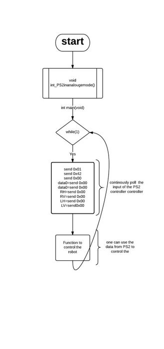
if u have understood the flowchart this will be quite easy
The code has only 2 function
1) int gameByte(short int command)
2) void int_PS2inanalougemode()
int gameByte(short int command)
{
short int i ; // variable used as counter
_delay_us(1);
short int data = 0x00; // clear data variable to save setting low bits later.
for(i=0;i<8;i++) // as 8 bytes are transferred i<8
{
if(command & _BV(i)) //each bit of command is ANDED with 1 one by one, thus value of that cmnd is if in condition
{
sbi(PORTB, PScommand); // if command is one command pin is set
}
else
{
cbi(PORTB, PScommand); // else command pin is made zero
}
cbi(PORTB, PSclock); // CLOCK LOW
_delay_us(1); // wait for output to stabilise
if((PINB & _BV(PSdata)))
{
sbi(data, i); // read PSdata pin and store
}
else
{
cbi(data, i);
}
sbi(PORTB, PSclock); // CLOCK HIGH
}
sbi(PORTB, PScommand);
_delay_us(20); // wait for ACK to pass.
return(data);
}
void int_PS2inanalougemode()-
this function puts the controller in analogue mode until it returns value 0x73 in 2nd byte which indicates that PS2 controller is in analogue mode if it doesn’t return its increments the counter and continues to put PS2 controller is in analogue mode
int main(void)
in main loop we simply poll the input of PS2 controller .
video
Source: Interfacing PS2 Controller With AVR -Bit Bang
- How do I get analogue values from the joystick?
You can get analogue value from the joystick which can be used to control the speed of the motor. - What is the best way to understand SPI communication?
The article suggests referring to avrbeginners.net or embedded.com for further understanding of Serial Peripheral Interface Bus. - Can I use internal SPI of AVR instead of bit banging?
Yes, you can check another guide titled Interfacing PS2 with AVR -SPI which uses the internal SPI of AVR. - How many pins are required for the hardware setup?
You have to connect only 6 pins given below for the hardware setup. - What command puts the PS2 controller into configuration mode?
The command 0x43 is used to go into configuration mode. - Which command turns on analog mode?
The command 0x44 is used to turn on analog mode. - How does the bit bang technique work?
Software directly sets and samples the state of pins on the microcontroller, responsible for all parameters like timing and levels. - What function initializes the controller in analogue mode?
The function int_PS2inanalougemode() puts the controller in analogue mode until it returns value 0x73 in the second byte.