Summary of Introduction to ADC in AVR Microcontroller | for Beginners
This tutorial explains ADC (Analog-to-Digital Converter) operation in AVR microcontrollers (ATmega8), covering ADC purpose, 10-bit successive approximation ADC features, input channels, reference and supply pins (AVCC, AREF), conversion formula, register configuration (ADMUX, ADLAR, ADCSRA), result reading (ADCH/ADCL), free-running vs single conversion modes, interrupts, and prescaler selection for proper ADC clock.
Parts used in the Introduction to ADC in AVR Microcontroller:
- ATmega8 microcontroller
- Analog sensors (temperature, light intensity, distance, position, force)
- AVCC supply pin
- VCC supply pin
- AREF pin (voltage reference)
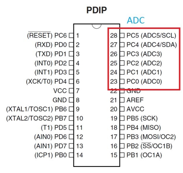
- ADC input pins on Port C (7 channels)
- ADC Data Registers ADCH and ADCL
- ADMUX register (ADC Multiplexer Selection)
- ADLAR bit (ADC Left Adjust Result)
- ADCSRA register (ADC Control and Status Register A)
- ADEN, ADSC, ADFR, ADIF, ADIE bits
- ADPS2:0 prescaler bits
In thid tutorial you will know everything ADC in avr microcontroller
Step 1: What Is an ADC?
An ADC, or Analog to Digital Converter, allows one to convert an analog voltage to a digital value that can be used by a microcontroller. There are many sources of analog signals that one might like to measure. There are analog sensors available that measure temperature, light intensity, distance, position, and force, just to name a few.
Step 2: How Work ADC in AVR- Microcontroller
The AVR ADC allows the AVR microcontroller to convert analog voltages to digital values with few to no external parts. The ATmega8 features a 10-bit successive approximation ADC.ATmega8 has 7 channel ADC at PortC. The ADC has a separate analog supply voltage pin, AVCC. AVCC must not differ more than ± 0.3V from VCC.. The voltage reference may be externally decoupled at the AREF pin. AVCC is used as the voltage reference. The ADC can also be set to run continuously (the free-running mode) or to do only one conversion.
Step 3: ADC Conversion Formula
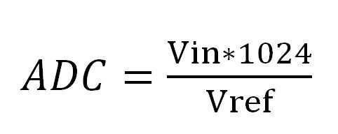
Where Vin is the voltage on the selected input pin and Vref the selected voltage reference
Step 4: How to Configure ADC in ATmega8?
The following Registers are used for implementation of ADC in ATmega8
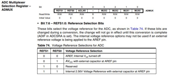
ADC Multiplexer Selection
Step 5: ADLAR Selection
ADC Left Adjust Result The ADLAR bit affects the presentation of the ADC conversion result in the ADC Data Register. Write one to ADLAR to left adjust the result. Otherwise, the result is right adjusted
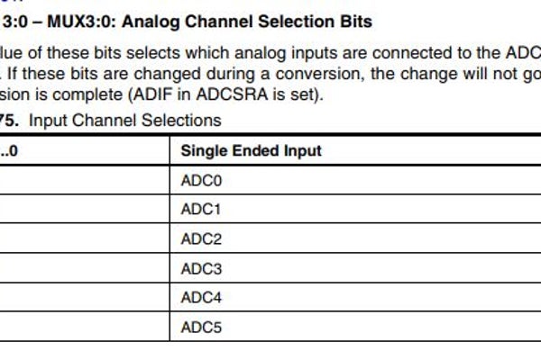
When an ADC conversion is complete, the result is found in ADCH and ADCL When ADCL is read, the ADC Data Register is not updated until ADCH is read. Consequently, if the result is left adjusted and no more than 8-bit precision is required, it is sufficient to read ADCH. Otherwise, ADCL must be read first, then ADCH. Analog Channel Selection Bits The value of these bits selects which analog inputs are connected to the ADC.
Step 6: ADCSRA Selection
• Bit 7 – ADEN: ADC Enable Writing this bit to one enables the ADC. By writing it to zero, the ADC is turned off
• Bit 6 – ADSC: ADC Start Conversion In Single Conversion mode, write this bit to one to start each conversion. In Free Running mode, write this bit to one to start the first conversion.
• Bit 5 – ADFR: ADC Free Running Select When this bit is set (one) the ADC operates in Free Running mode. In this mode, the ADC samples and updates the Data Registers continuously. Clearing this bit (zero) will Terminate Free Running mode.
• Bit 4 – ADIF: ADC Interrupt Flag This bit is set when an ADC conversion completes and the Data Registers are updated. The ADC Conversion Complete Interrupt is executed if the ADIE bit and the I-bit in SREG are set. ADIF is cleared by hardware when executing the corresponding interrupt Handling Vector. Alternatively, ADIF is cleared by writing a logical one to the flag.
• Bit 3 – ADIE: ADC Interrupt Enable When this bit is written to one and the I-bit in SREG is set, the ADC Conversion Complete Interrupt is activated.
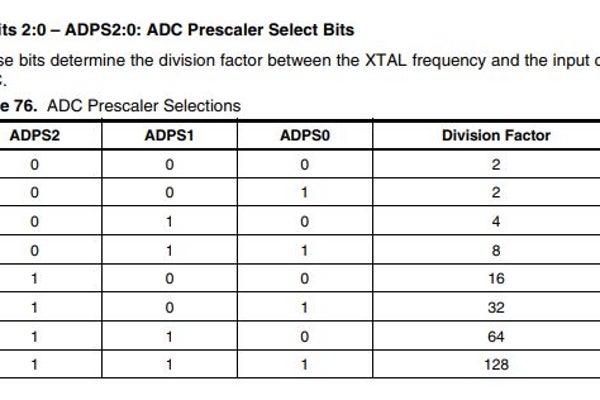
• Bits 2:0 – ADPS2:0: ADC Prescaler Select Bits According to the datasheet, this prescalar needs to be set so that the ADC input frequency is between 50 KHz and 200 KHz. The ADC clock is derived from the system clock with help of ADPS2:0 These bits determine the division factor between the XTAL frequency and the input clock to the ADC.
Source: Introduction to ADC in AVR Microcontroller | for Beginners
- What is an ADC?
An ADC converts an analog voltage to a digital value usable by a microcontroller. - How many bits is the ADC in ATmega8?
The ATmega8 features a 10-bit successive approximation ADC. - How many ADC channels does ATmega8 have and where are they located?
ATmega8 has 7 ADC channels located at Port C. - What pins relate to ADC power and reference on ATmega8?
AVCC is the analog supply voltage pin, VCC is the digital supply, and AREF is the external voltage reference pin. - How is the ADC conversion result accessed?
The result is found in ADCH and ADCL; if left adjusted and 8-bit precision suffices, read ADCH only, otherwise read ADCL first then ADCH. - What does the ADLAR bit do?
ADLAR left adjusts the ADC result in the data registers when set; otherwise the result is right adjusted. - How do you start an ADC conversion?
Set the ADSC bit in ADCSRA to one to start a conversion (single or first conversion in free running mode). - How do you enable the ADC interrupt?
Write one to ADIE in ADCSRA and ensure the I-bit in SREG is set to activate the ADC Conversion Complete Interrupt. - What is the purpose of the ADC prescaler bits ADPS2:0?
ADPS2:0 set the division factor from the system clock to derive the ADC clock; they must be chosen so the ADC input frequency is between 50 kHz and 200 kHz. - What is free running mode for the ADC?
When ADFR is set, the ADC continuously samples and updates the data registers in free running mode.