Hello Everyone!,
Welcome to our group instructables page. Here, we’ll break down all the steps you’ll need to build the “It’s 5 O’Clock Somewhere” portable clock.
What is it?
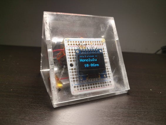
It’s a portable clock, connected to your local wifi, or paired with your phone, to show you the current time and where in the world it’s 5 o’clock. A tongue in cheek take on the expression “it’s 5 o’clock somewhere”, which alludes to the time in which the end of the work day has arrived, and happy hour has begun. Our device is a constant reminder that somewhere, someone is enjoying the end of their day.
What does it do?
It displays the name of a city in which it is currently 5 pm, along with the current time in your timezone. The electronics are visible through a pyramid shaped case, made from laser cut acrylic. This makes for a great portable desktop show piece.
How Does it do it?
The device makes use of the Particle Photon to connect to WIFI and determine the user’s location. The photon is programmed to capture the user’s time and location, and then determine other timezones accordingly. The time and city then gets displayed on a 0.96″ OLED screen.
Parts List
Particle breakout for lipo battery
Lithium Ion battery (1200mA)
0.96″ OLED display (this one)
2 x 1/4 sized protoboard (we recommend this kind)
7 x 2″ pieces of 22awg wire
–//Encasing//–
3mm thick acrylic sheet (one sheet of 15″x13″ acrylic allows for enough material for 4 of these boxes)
Double sided tape
(see step 4 for complete bill of materials)
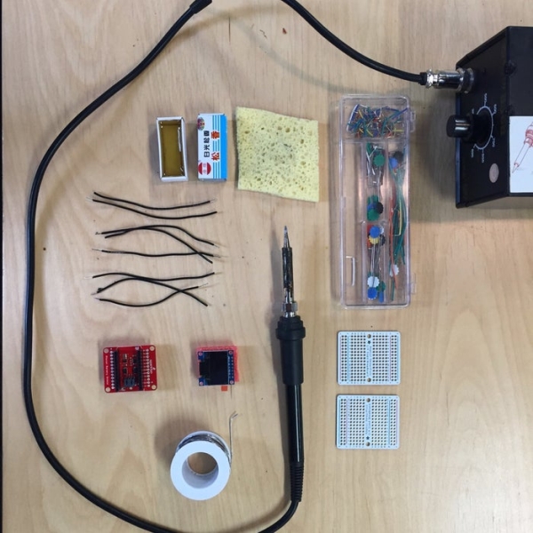
Tools list
Soldering Iron
Lead-free Solder
Sponge
Flux
A laser cutter (we recommend finding a local shop that can do this for you).
Exacto knife
Gorilla brand super glue
This project was created in collaboration by Jacob Cram, Colin Borins, Nathaniel Leslie, and Luke Garwood.
Step 1: Soldering
Since there are two protoboards, we’re going to call them protoboard1 and protoboard2 for clarity. Also, we’re assuming you’re working with the adafruit 1/4 sized protoboards, if you’ve chosen another set of protoboards then the rows and numbers may not line up exactly, but hopefully you can follow along anyway.
Connect your OLED screen to protoboard1. Solder the OLED screen’s pins to protoboard1’s row B, holes 5 through 11. B5 — CS, B6 — DC, B7 — RES, B8 — D1, B9 — D0, B10 — VCC, B11 — GND.
Solder one end of approximately 2 inches of wire to A5
Repeat this with the 6 other pieces of wire, connecting one end of each wire to A6 through A11.
Now take your lipo breakout module and line it up with the holes of protoboard2 (we’ll be inserting the wires through both the protoboard and the breakout module and soldering them in place). *the reason we need the second protoboard is so that the device sits evenly on both sides. If you’d like to alter the design, you may not need this.
- Take the wire connected to A5 (or CS on the screen) and thread through to D4 on the breakout, solder in place.
- Take the wire connected to A6 (or DC on the screen) and thread through to D3 on the breakout, solder in place.
- Take the wire connected to A7 (or RST on the screen) and thread through to D5 on the breakout, solder in place.
- Take the wire connected to A8 (or D1 on the screen) and thread through to A5 on the breakout, solder in place.
- Take the wire connected to A9 (or D0 on the screen) and thread through to A3 on the breakout, solder in place.
- Take the wire connected to A10 (or VCC on the screen) and thread through to 3V3 on the breakout, solder in place.
- Take the wire connected to A11 (or GND on the screen) and thread through to GND on the breakout, solder in place.
That’s it! You’re electronics are all set!
Step 2: Acrylic Box
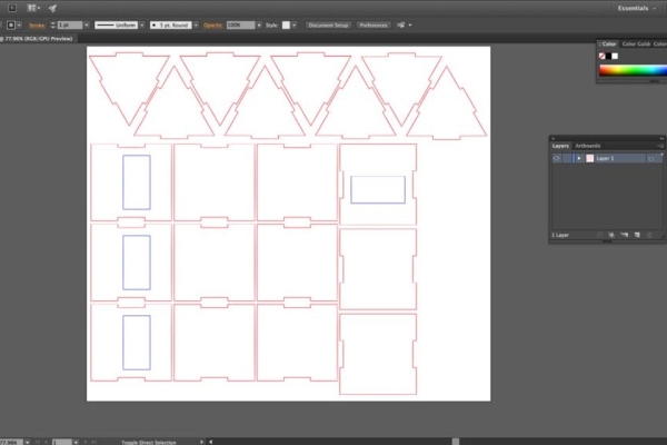
- Download the file we’ve provided in the Files and References section
- Take that file to your local laser cutter.
- Once you have the pieces, start by peeling away the protective vinyl from the acrylic
- Once all the pieces are peeled, take one of the triangular pieces, and apply glue to one of the edges.
- Take the rectangular piece with the hole cut out, and connect it with the notched side on the triangular piece you just put glue on.
- Once dry, look to see which end of the rectangle the hole is closer to. This edge is where the bottom of the device will go, we want to attach the bottom last, so apply glue to the other edge of the triangle.
- Connect the rectangular piece again.
- When dry, apply glue to two sides of the second triangular piece, and connect it opposite to the first triangle.
*Suggestion for when you put the electronics in the box. We’ve scored two slits the width of the electronics (a little wider than your battery), on the bottom piece with an exacto knife. This forms two grooves for the protoboards to sit it. Now you can apply glue to the bottom edge of the protoboards and set them in those two grooves for a better stick. We also applied a bit of double sided tape to the bottom of the Lipo battery so that it can also be stuck to the bottom piece of the box.
Step 3: Programing the Photon

If you’re brand new to Particle Photons and you’ve opened yours up for the first time, we recommend following the steps outlined in Particle’s documentation to help get you started and connected to WIFI. You can find directions at https://docs.particle.io/guide/getting-started/start/photon/ .
Then download the desktop version of Particle Photon’s IDE (integrated development environment). You can find it at https://www.particle.io/products/development-tools/particle-desktop-ide.
Grab the code we’ve provided from our Git Hub at https://github.com/JacobDotCram/5oclocksomewhere, choose to download it, and then unpack the zip file.
From the Photon IDE, open the folder entitled “5oclocksomewhere-BranchOne” from the unpacked zip file. Opening this folder will allow you to integrate all the required libraries.
On the left hand side, there’s a list of all the files included in the “5oclocksomewhere-BranchOne” folder, you’ll want to open the fivepm.ino file if you want to make any modifications.
Make sure your device is connected to your computer, and that it’s selected in the bottom toolbar (click to add it from the list if it’s not).
Compile and flash the code to your device by clicking the lightning bolt in the top left corner.
And there you go!
Step 4: Files and References
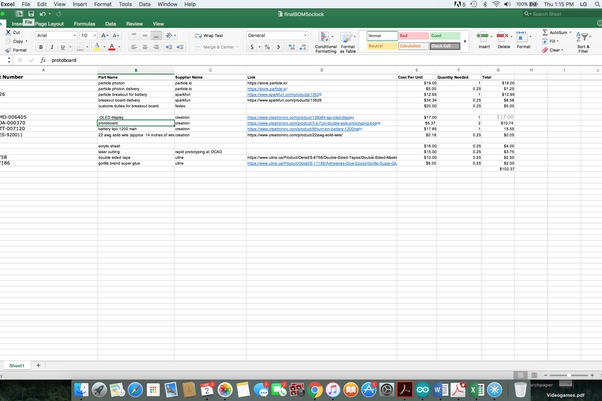
Files included here are a bill of materials, a fritzing file with the circuit diagram (http://fritzing.org/home/), and the illustrator file for the acrylic pyramid case
Source: It’s 5 O’Clock Somewhere