This Instructable was designed to answer the question: how do I get started in microcontrollers? Now, in clear, simple English, you can learn what a microcontroller is, and how to use one. You will learn how to make everything that you need to get started. This does require a Windows PC with at least one USB port.
In eighteen easy steps, you will learn what a microcontroller is, how to put one together, how to program it and how to interface the microcontroller to simple input and output devices. All of the components, including the microcontroller itself, are are easily obtained from many different sources, or you may purchase a complete kit from GranzTronix (https://www.tindie.com/products/Granzeier/introduction-to-microcontrollers/.) You will get all of the parts that you need in the kit, but you do not need the kit – all of the experiments may be completed with the information provided in this ‘ible.
Your introduction text ebook, including the assembly instructions for the purchased kit (skip this part if you build your own following this Instructable,) all quizzes and answers and the sample programs, may be downloaded from our web site at: http://files.granzeier.com/Downloads/2313ES.pdf. The steps in this ‘ible are like a Reader’s Digest version of the ebook.
Required Parts:
You will need a few parts for this project. You can get most of these from your local Radio Shack, or you may mail order them from any of many different supply houses.
- a breadboard – you will need at least an 800-terminal breadboard, but that will give you limited expansion space. The breadboard I show in these pictures provides two 800-terminal breadboards with dual power rails for each one.
- an AVR programmer – we use the USBASP programmer here. I routinely find these on eBay for well under $5.00 delivered. If you choose a different model, you will need to modify the directions in this ‘ible accordingly.
- a way to connect the programmer to your breadboard. In step 4, I mention two ways to accomplish this.
- 3 low-voltage, low-current LEDs (plus one more if you would like a pilot light to indicate when your dev kit is powered.
- 3 (or 4 if you use the pilot light) 360 ohm, 1/4 to 1/8 watt resistors to limit the current through the LED.
(You can get a pack of 6 LEDs and resistors from https://www.tindie.com/products/Granzeier/led-prototyping-pack/.) - 3 small NO, SPST, Momentary action pushbutton switches – one for the reset circuit, and two for experiments. (https://www.tindie.com/products/Granzeier/pushbutton-switch-pack-/)
- a small speaker. (included in: https://www.tindie.com/products/Granzeier/digital-interface-pack/)
- An Atmel AVR ATtiny2313 microcontroller (this is also included in the GranzTronix kit.)
- optional – a 5V power source. Your dev kit can be totally powered by the programmer, this is only needed if you would like to disconnect your computer and take your experiments out to show them off. The kit comes with a battery box, using 4 AA-cells for a total of 4.8V or 6V, depending upon the type of cells used.
As mentioned earlier, you may build this system, and go through all of the experiments shown here (and the others in the book,) or you may purchase a complete set of all parts, including a professionally developed PCB (printed circuit board,) from GranzTronix (https://www.tindie.com/products/Granzeier/introduction-to-microcontrollers/.)
Step 1: What Is a Microcontroller?
Before you can design with a microcontroller, you really need to know what one is. Microcontrollers are all around you, although you may not even realize it. Many people seem overawed by the thought of a microcontroller. A while ago, I spoke to a woman who, when I told her that I work with microcontrollers, replied that those things were far beyond her. I responded that maybe she could not design with them yet, but that she uses those small computers all the time. She appeared to think that I was nuts to suggest that she could even be involved, in any way, with that kind of “high tech” stuff. These microcontrollers are the brains in many products around the home and office. These microcontrollers can be found in watches, microwave ovens, telephones, cars and trucks, DVD players and robots, in fact almost every product that has a display will use at least one of these microcontrollers. So, most people in industrialized nations are already microcontroller users, even though they don’t think of themselves that way.
What is a computer?
A microcontroller is a type of computer, so what is a computer? All computers are made up of four major units. These include the Input unit, the Output unit, the Central Processing unit and the Memory unit. The Input unit is the way that the computer gets the data on which it will do it’s work. Most people know about input devices attached to their desktop computers, devices like their keyboard and their mouse. The Central Processing unit performs the work of running the computer’s programs. This is made up of a Control Unit and an Arithmetic/Logic Unit (also called an ALU). Together these two units make up the Central Processor Unit, or CPU. While working, the CPU keeps it’s instructions, or the program, along with the data on which it is working, in the Memory unit. After the computer does it’s computing, it will present the results of that work thru the output unit. Some of the output devices attached to your desktop computer would be the video display and the printer. A microprocessor combines the two parts of a computer’s CPU (the Control Unit and the ALU) into one single integrated circuit (IC) or chip.
A computer can do a vast number of different jobs. The computers with which you may be most familiar are the ones that sit on or next to your desk and run Windows or Linux or maybe MacOS. These general-purpose computers will help you type a letter or term paper, balance your checkbook or your accounting books, or maybe research different topics by letting you browse the Web. A whole other type of job is for the computer to run (or control) a piece of equipment. By connecting the electrical lines in a computer’s input unit to different switches or sensors, and connecting the electrical lines in that computer’s output unit to lights, motors and other such devices, a computer can control things like an assembly line, a microwave oven, a stereo, or even something like a plane or space ship. In fact, anything that can be operated by one or more switches can be connected to an output line and controlled by a computer. These computers, which are dedicated to the control of equipment, are called Control Computers, or simply Controllers.
In the same way that a Microprocessor combines the two parts of a Control Unit into one IC, a Microcontroller combines the four parts of a computer onto one single IC – these ICs are specially crafted to include things useful for controlling equipment. Thus, they are called microcontrollers.
As you can see, there is nothing inherently complex about microcontrollers; they are simply small control computers integrated onto a single chip. The microcontroller on your Tiny2313 Experimenter System is an IC (or chip) from Atmel, called the AVR ATtiny2313A.
Step 2: Tell Me What You Want Me to Do.
A computer is only as useful as a doorstop between uses, without a program to tell it what to do. The process of giving the computer instructions to perform a task is called programming. A program is pretty much just a list of instructions to the computer. Since a computer only knows about the presence or absence of voltage levels, the Tiny2313 chip uses voltage levels to tell it what to do. All of the instructions and data inside the Tiny2313 are actually voltage levels of either (about) 5 volts or 0 volts. We represent these voltage levels as ones and zeros for our convenience, not for the computer’s convenience. However, as good as those representations are, they are still not very easy for humans. Shortly after computers started coming on the scene, humans wrote tools to help with programming these machines. Some of the first tools were language translators, which took a more human-like language, and translated that into ones and zeros for the computer. Higher level languages, or languages which are closer to human languages, make it easier for a programmer to tell the computer what to do. The process of translating these “high” level languages into the computer’s machine language is called compiling.
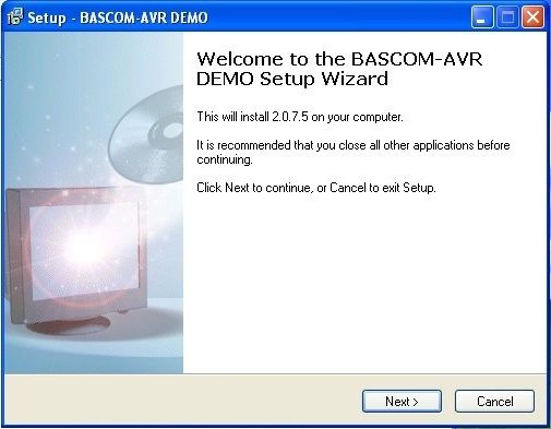
MCS Electronics produces a language compiler called BASCOM-AVR for Atmel’s AVR family. BASCOM is a variant of the BASIC programming language. This language was invented by two professors, at Dartmouth College in the 1960s, specifically for beginners. In fact, the name BASIC is an acronym, which stands for Beginners All-purpose Symbolic Instruction Code; in other words, it is a general (All-purpose) Code, for Beginners to give the computer Symbolic Instructions to perform a job. It was designed to be easy to learn and to allow non-computer students to quickly be able to write programs for the university’s computer system. The free trial version, of this BASIC, is limited only in the size of the program. This limit is 4K bytes, which makes BASCOM-AVR an easy match for learning about microcontrollers with the Tiny-2313. You can download this language from MCS’s web site.
Getting the Latest Version
In this book, we will be installing and using BASCOM-AVR. You will need to get the newest version from MCS Electronics, the publisher:
1. Go on the web to http://www.mcselec.com and click on Downloads on the left side of the screen.
2. On the Downloads page, click on the BASCOM link at the bottom of the Downloads list on the right side of the page.
3. On the BASCOM page, click on the BASCOM-AVR link at the top of the list of downloads.
4. On this page, click on the link to download the BASCOM-AVR Demo version.
5. On the Terms and Conditions page, click the radio button for “I agree” and then click the button to proceed. This will open the download dialog box, make sure that the “Save file” radio button is selected and click the OK button.
6. In the Save to dialog box, select your desktop and click the Save button.
7. Click on the back button on your browser to return to the BASCOM AVR download page and also download the manual. This has lots of information and is very well organized. 8. Also, on the BASCOM-AVR page, you will find more information about BASCOM-AVR, including articles written about this compiler.
9. Close, or minimize, your browser.
10. Follow the directions to install BASCOM-AVR (you may follow the directions from MCS Electronics, or those in the ebook.)
Step 3: You’re Driving Me Nuts.
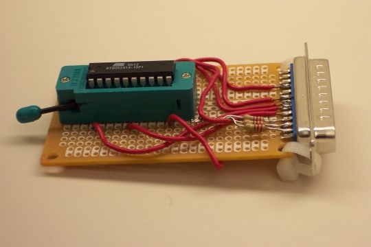
While you will be writing your programs for the Tiny2313 on your PC, you will need to transfer that program to the Tiny2313 chip, itself, in order to let the controller run the program. To put the program into your microcontroller, you must have some way to get the program from your PC into the chip. The way engineers used to do this was by taking the chip and placing it into a special device called a programmer. There is a picture of my old Fun Card AVR programmer for ATtiny2313 controllers above. After running the programming software, you would take the chip with the program in it and place it into your circuit. If, or rather when, you discovered an error in your program, you would take the chip out of the circuit, put it into a special device to erase the program (often taking hours), put it back into the programmer, and start the whole process again. This would happen over and over until either you got the program correct, or (often) you just got tired and quit.
We will be using what is called an ISP Downloader Cable. The ISP abbreviation stands for In System Programmer; this is a way that engineers have developed to get around that old way of using a dedicated programmer. We have a special ISP connector on the microcontroller board, and will just connect the programming cable to the board in order to download the program. All of the programming activity is accomplished on the circuit board and the microcontroller chip itself. No need to pull the chip out and move it around.
The ISP that you ordered with your kit is called a USBASP Programmer. We mentioned that programmer earlier, when talking about how to set up BASCOM-AVR.(If you purchased a different model, you will need to modify this Instructable appropriately.)
In order for your computer to be able to use a piece of hardware, you will need to tell it how. The way that you do this is to load a program, called a driver. A driver is just a program that tells your computer how to talk to an attached device. There are drivers, built in to Windows, to tell your computer how to use the mouse, how to read the keyboard, how to display pictures and text on the screen. The USBASP Programmer is not something that everyone uses, though and so, we need to install the driver for that Programmer.
As you did with the BASCOM compiler itself, you will need to download the driver for your USBASP Programmer. To do this, follow the directions in the ebook, or at: http://www.protostack.com/blog/2011/05/usbasp-driver-for-windows-7-and-windows-vista-x64/.
Step 4: Let’s Build This Thing.
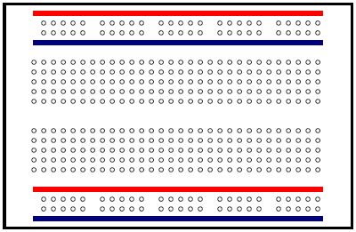
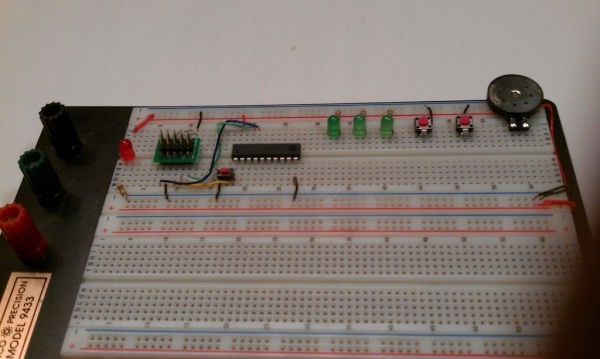
Start off with a breadboard.
If you do not want to get a kit, you will need to build your own Development Kit (dev kit.) The best start for your dev kit is to use a solderless breadboard. If you do not know what a breadboard is, take a look at my breadboard page: http://projects.granzeier.com/what-is-a-breadboar… You will want to use the pictorial diagram above to see where to place the jumper wires. You will only need three components: the programmer connector, the ATtiny2313 itself, and an SPST, normally-open, momentary pushbutton switch for the reset button. I used one of the AVR Breadboard Adaptors (https://www.tindie.com/products/Granzeier/breadboard-avr-isp-adapter-kit/,) but you could also use The Real Eliot’s USB Ghetto Development Environment (https://www.instructables.com/id/EDRQZ56F5LD8KDX/,) or any other AVR programming system.
Once you place the components on the breadboard, it’s just a matter of connect the dots. You may want to double-check your connections using the AVR ATtiny2313 datasheet (http://www.atmel.com/Images/doc8246.pdf – the 2313 and the 2313A are very similar, there will be no difference in the wiring. You will just need to make tiny changes to your program (every place that the program mentions Tiny2313A, you will just use Tiny2313 if you use the older chip.)
Step 5: Connect Your 2313 to the World – Pt. 1.
Let’s shine a little light on the subject.
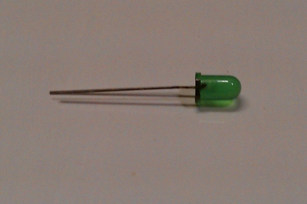
An LED is a device which allows electricity to flow in only one direction, and when electricity does flow, it gives off light. You can learn more about LEDs and how they work, at my store: https://www.tindie.com/products/Granzeier/led-prototyping-pack/.)
Take your LEDs and trim the leads to about 1/4″ (or about 1 cm.) It’s a good idea to mark the cathode (negative lead) of your LED with a black marker pen, or a drop of fingernail polish – this can help you to identify the cathode after you cut the leads. You will be placing the LEDs’ leads into the breadboard spanning two different rows. Place a 360 ohm (anywhere between about 220 ohms and about 470 ohms will work fine) resistor in one of the holes in the row with the LEDs cathode, and the ground power rail. The anode (or positive lead of the LED) will be left free so that you can connect the LED to your Tiny2313 microcontroller.Take a look at the photo of the LED/resistor pair in the breadboard to see what I am describing.
Next, move down the board (away from the Tiny2313 circuitry,) about one inch, and add a second LED/resistor pair. Now, add one more LED/resistor pair, about one more inch down the board. This will give you three LEDs that your microcontroller can turn on and off.
While I have used all green LEDs in my dev kit, and in the Tiny2313 Experimenter System in my store, there is no reason that you could not use another color LED. In fact, you could even use three different color LEDs.
Step 6: Connect Your 2313 to the World – Pt. 2.
You really know how to push my buttons.
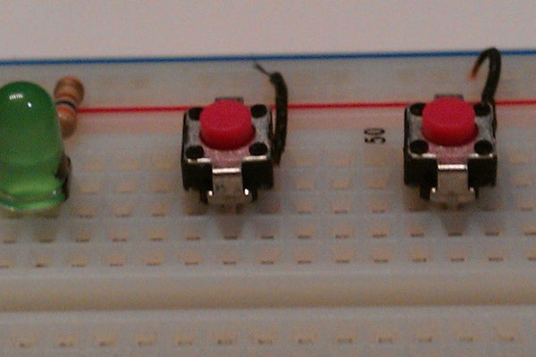
To provide input to your Tiny2313, we will use simple pushbutton switches. These are called Normally Opened (NO,) SPST, momentary, pushbutton switches. If you take a look at the schematic diagram of the switch above, you will see that the switch consists of two terminals and a small conductor; when you push the button, the small conductor is pressed against the two terminals allowing electricity to flow. Later on, we will see how this allows the Tiny2313 to tell when the button is pressed.,
Take a look at the photo above, and you will see that the pushbutton is placed on the breadboard very much like the LED. Use a short jumper wire to connect one terminal of the switch to ground, and leave the other terminal free for connecting to the Tiny2313. Place this switch circuit just down from the last LED/resistor pair, on the breadboard.
Repeat this one more time so that you have two pushbutton switch circuits.
Source: Learn About Microcontrollers