Summary of LED Cube 3x3x3 With ATMEGA8
This article details the construction of a 3x3x3 LED cube using an ATmega8 microcontroller. The project involves soldering LEDs into three horizontal levels and nine vertical rows, connecting them to a veroboard for control via multiplexing. It covers mechanical assembly on wood, electrical connections without external resistors (due to the microcontroller's current capacity), and programming logic using AVR assembly code to create visual effects.
Parts used in the LED Cube 3x3x3:
- 27 LEDs matte
- Microprocessor ATmega8
- Electrolytic capacitor 47UF 16V
- Veroboard
- Small wood board at the minimum 10x10cm
- 50 cm wire tinned
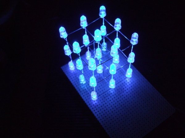
An interesting project and already much discussed in the forums and also in videos.
Although it appears complex,it is a simple idea and fun very purpose.
Mounting material:
– 27 LEDs matte
– Microprocessor ATmega8
– Electrolytic capacitor 47UF 16V
– Veroboard
– Small wood board at the minimum 10x10cm
– 50 cm wire tinned
(excuse me, I’m portuguese and my english is not very famous :p)
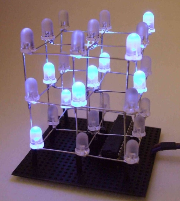
Step 1: Theory of Operation of the Array of LEDs
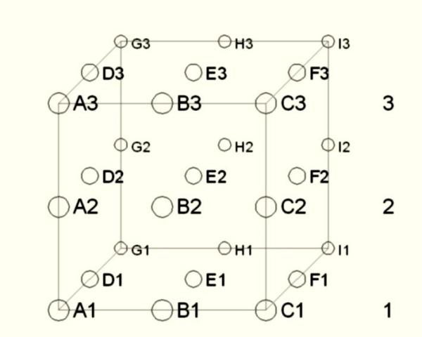
The array of LEDs is comprised of 3×9, where three levels are horizontal, and 9 are the vertical rows.
Each LED is turned on a level with a common cathode and each vertical line is connected with a common anode.
So if we want to illuminate a particular LED, just put the level of the 0V line and gave a positive voltage.
To be able to generate an effect of several LEDs on, they have to be powered by multiplexing, a relatively high speed does not seem to be blinking and have a softer light.
As the ATmega8 supports connection of LEDs directly to its pins with a good current, there is no need to put limitation resistors or transistors driver.
Step 2: Creating Horizontal Levels of the LEDs (negative)
Here becomes more complicated as the presentation of the outcome depends on the linearity on which the LEDs are soldered.
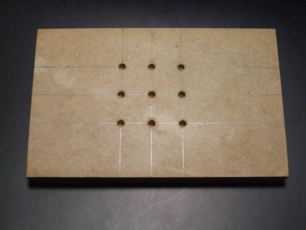
To make it to nine holes with a diameter of 5mm, a board 2cm intervals, where the LEDs can be confident, to be soldiers and bend the terminals in a specific way.
Cathode (negative):
After the LEDs are fixed on board, can be double the cathodes in order to get all nine together, taking care not to bend the center. As the terminals of the LEDs are not sufficient to make the 12 connections, you can use one wire tinned in order to be more esthetic final result.
Anode (positive):
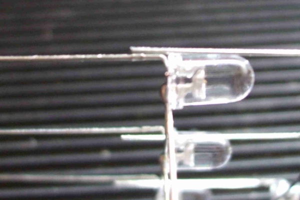
In relation to the anode, must all be folded the same way, so that when you turn the LEDs below it easier to make its welding. Then each anode of the LED, is bent out of its center, and then bent upward at the end of this limit.
These processes are performed for the three horizontal levels in the same way, removing the cathode from the center that will connect directly to Veroboard, creating the negative phase of this level.
Step 3: Creating the Vertical Rows of LEDs (positive)
Now the three horizontal levels must be attached from the vertical rows, which are the anodes.
In this case the level of the top is attached to the board where they made the holes.
Weld in the center of the cathode terminal, an enameled wire so that it is long to reach Veroboard.
The following relates to grasp the 2nd level which is fixed to the board, solder to all the anodes of the LEDs that were upright, overlapping about 10mm between these two levels.
After being welded, as can also weld the central cathode in order to reach the Veroboard.
With the lower level, the process is similar to the 2nd level
Here we have the hub already fitted and can follow links in the construction of Veroboard.
Step 4: Preparing Veroboard
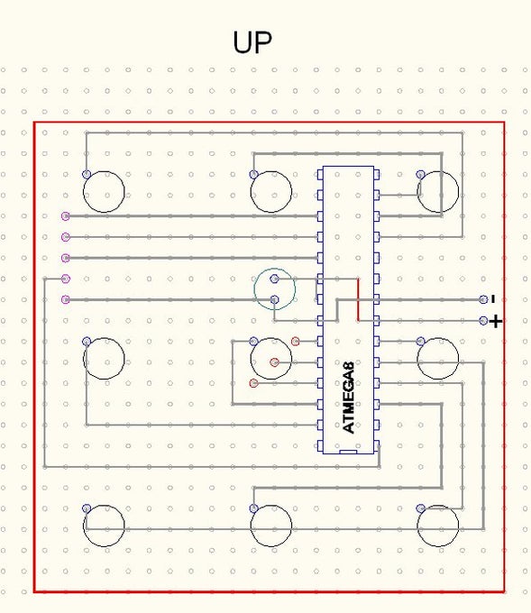
This card is pre-drilled very practical to do this kind of setups.
Has 5.5 cm x 5.5 cm and in the attached picture you can see the location of the holes, which aids in welding wire your circuit on the tin.
Given the orientation of the atmega 8 and the condenser, it is advisable to place a support for this microprocessor. This microprocessor has an ISP interface, which allows its programming via 5-wire circuit, without the need of a crystal oscillator.
After the entire circuit to be soldered, it is advisable to have mount the microprocessor, because when you take the cube of LEDs on top, it becomes complicated apply it.
Step 5: Assembling the Cube of LEDs on Veroboard
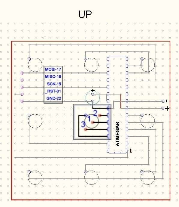
Following the photo attached, plug the hub is not complicated, taking into account the connection of the cathode of each level to the hole.
For this, they were numbered to facilitate their identification in this phase.
After welding the anodes of each vertical row over the condenser, the cube of LEDs is ready to be programmed.
Power can range from 4.5V to 5V, advising not to keep the LEDs lit a lot of time in your schedule, the microprocessor delivers 40mA for each output line of doors, which would burn the LED for this might be a resistance soldier temporarily 330R between the outputs of the microprocessor and the cathodes, which are 3.
Step 6: Programming
Finally completed this setup, it is now one of the programming process; there is much documentation to program this type of microprocessor on the Internet.
This is the map of addresses for access to ports, is formatted in AVR, and a corresponding LED to light up, just pick a position matrix of the “PtC” and the same position of “PtD”:
PtC:
.db 0b00000101, 0b00000101, 0b00000101, 0b00010101, 0b00001101, 0b00000101, 0b00000101, 0b00000101, 0b00000101, 0b00000110
.db 0b00000110, 0b00000110, 0b00010110, 0b00001110, 0b00000110, 0b00000110, 0b00000110, 0b00000110, 0b00000011, 0b00000011
.db 0b00000011, 0b00010011, 0b00001011, 0b00000011, 0b00000011, 0b00000011, 0b00000011, 0
PtD:
.db 0b00001000, 0b00000010, 0b00000100, 0b00000000, 0b00000000, 0b00010000, 0b00100000, 0b01000000, 0b10000000, 0b00001000
.db 0b00000010, 0b00000100, 0b00000000, 0b00000000, 0b00010000, 0b00100000, 0b01000000, 0b10000000, 0b00001000, 0b00000010
.db 0b00000100, 0b00000000, 0b00000000, 0b00010000, 0b00100000, 0b01000000, 0b10000000, 0
Knowing that this is the concept of the multiplex circuit, it is a matter of time if you can master this technique and create stunning visual effects.
You can see a demonstration of some effects built with this cube of LEDs in this site:
http://www.youtube.com/watch?v=9jQHUWXAez0
Source: LED Cube 3x3x3 With ATMEGA8
- How does the LED array operate?
The array uses a 3x9 configuration where horizontal levels have common cathodes and vertical rows have common anodes, utilizing multiplexing to illuminate specific LEDs. - Does the project require external resistors or transistors?
No, because the ATmega8 supports direct connection with sufficient current, so no limitation resistors or transistor drivers are needed. - What is the recommended power voltage range?
Power can range from 4.5V to 5V, though keeping LEDs lit for long periods is advised against to prevent burning. - Can I program the microprocessor without a crystal oscillator?
Yes, the ATmega8 has an ISP interface that allows programming via a 5-wire circuit without needing a crystal oscillator. - How should the LED terminals be bent during assembly?
Cathodes are doubled together while anodes are folded uniformly, bent out from the center, and then upward to facilitate welding. - What is the maximum current each output line of the microprocessor delivers?
The microprocessor delivers 40mA for each output line of doors. - What happens if the LEDs stay lit for too long?
The microprocessor might burn the LED due to the high current output, which could be mitigated by adding a temporary 330R resistor. - What format is the programming map addresses provided in?
The map of addresses for access to ports is formatted in AVR.