Summary of LED DISPLAY SPEED METER CIRCUIT WITH AT89C51
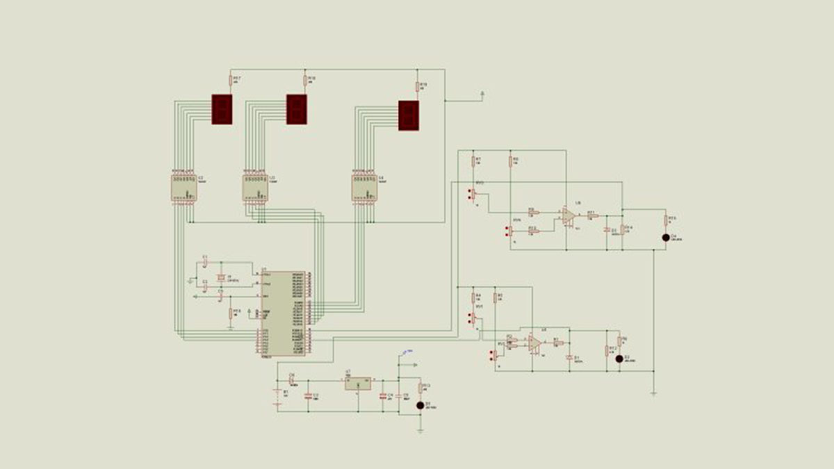
Speed Meter Circuit uses an AT89C51 microcontroller to read sensor signals, convert them via op-amps and comparators, and display speed on 7-segment LEDs. Power is supplied from 12V, regulated to 5V with a 7805 for the microcontroller and display; a potentiometer sets comparator reference. Keil µVision3 was used for programming; Proteus ISIS simulation and source files are available.
Parts used in the Speed Meter Circuit:
- AT89C51 microcontroller
- 7-segment LED display
- Op-amps (for sensor signal conditioning)
- Comparators
- Potentiometer (reference voltage adjustment)
- 7805 voltage regulator
- 12V DC power supply
- Zener diode 5.1V (voltage reference/protection)
- Sensor (speed/position sensor)
- Supporting passive components (resistors, capacitors)
Speed Meter Circuit consists of four parts. These Supply solid floor Sensor sensor, microcontroller and microcontroller solid hexadecimal numbers we obtained from the 7-segment display technology with time code converter solid. Program Keil µVision3… Electronics Projects, LED Display Speed Meter Circuit with AT89C51 “8051 example, avr project, keil example, microcontroller projects, “
Speed Meter Circuit consists of four parts. These Supply solid floor Sensor sensor, microcontroller and microcontroller solid hexadecimal numbers we obtained from the 7-segment display technology with time code converter solid. Program Keil µVision3 AT89C51 microcontroller.
Supply DC 12V working with solids. However, by 7805 we have achieved solid display technology and microcontroller is supplied with 5V regulated. 12V opam the feeds OPAMPs from sensors to information received by the comparator works as and with the potentiometer we determine the reference voltage sensors have achieved with voltage compare output 0-12’re getting 12V to microcontroller directly would not go zener 5.1V a fix and this information logic 5V and 0V used it as we are .
AT89C51 SPEED METER SCHEMATIC
source: https://320volt.com/en/ds89c430-ile-7-segment-display-gostergeli-hiz-olcumu/ AT89C51 LED Display Speed Meter Circuit keil source code and proteus isis simulation schematic files: led-display-speed-meter-circuit-with-at89c51.rar
- What microcontroller is used in the speed meter?
The AT89C51 microcontroller is used. - How is the system powered?
A 12V DC supply powers the system, with a 7805 regulator providing 5V for the microcontroller and display. - How are sensor signals processed?
Sensor signals are conditioned by op-amps and fed to comparators; a potentiometer sets the comparator reference voltage. - How is the display driven?
Hexadecimal numbers from the microcontroller are displayed on a 7-segment LED display. - What software is used to program the microcontroller?
Keil µVision3 is used for programming. - Is there a simulation or source files available?
Proteus ISIS simulation schematic and source files are available as led-display-speed-meter-circuit-with-at89c51.rar. - Why is a Zener diode mentioned?
A 5.1V Zener is used to fix or protect the logic voltage and ensure 0V/5V logic levels for the microcontroller. - Can the microcontroller accept 12V directly?
No, the microcontroller uses a regulated 5V from the 7805; 12V must not be applied directly.