Introduction
Our project utilizes an array of LEDs that work as light sensors to generate a musical tone, simulating a piano keyboard.
The basic idea is to use LEDs as both emitters and sensors. For our project specifically, we used a total of 63 LEDs, 9 for each of the seven natural keys. Only the middle LED served as photodetector when the key was pressed, absorbing light from the other LEDs reflected from the finger. We then used the Karplus-Strong algorithm for sound generation, all programmed in C. The tone was passed through an audio amplifier, and can be listened through headphones or speakers connected to the audio jack.
We chose this project because we wanted to do something with LEDs as sensors, and specifically chose music because of our interest in this matter.
High level design
� Rationale
� Background Math
� Logical Structure
� Hardware/Software Tradeoffs
� Standards
� Patents
Rationale
The rationale behind this idea consists of using a diode in a 3 step process, as shown in the following schematic. Each step is approximately 1 millisecond long. The upper pin will starts at Vcc and stay there for one millisecond (step one), and then drop to ground for two milliseconds (step two and three). The lower pin will start at ground for step 1, then rise to Vcc for the length of step two and finally the diode will discharge exponentially due to the hole-electron generation due to the incident light on the LED (8 pin leakages).
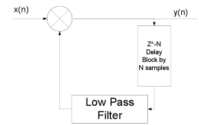
For the sound generation we will use the Karplus-Strong algorithm developed in the 80s, which is computationally simple. It is a method of physical modeling a string that simulates the sound of some types of instruments, including the piano. It uses a low pass filter and a delay block, which we will implement in software. A schematic of how it works is shown below.
The output frequency for each note was calculated from the formula,
Where N is the length of the delay line, and fs is the sample frequency at which the loop is updated.
For this project we used a sample rate of 8 kHz. While this sample rate causes some quantization of possible frequencies since the delay line has only integer lengths, we were still able to get relatively accurate frequency synthesis.
The input x(n) is excited using a signal noise until the delay line is filled to excite the entire system.
The low pass filter is simply a moving average, which has the equation below
where g is a loss factor that must be less than 0.5 for the system to be stable. By making g smaller the signal will die out faster.
Above is a block diagram of the system wiring. The MCU interfaces with the LED array to get the human touch interfaces, and then produces a sound output that is passed through the audio amplifier to the speakers.
Hardware/Software Tradeoffs
We implemented a low pass filter in software for the Karplus-Strong algorithm. Even though low pass filters can be made with hardware, for this part it was necessary to do it in software.
Also, while we implemented the Karplus-Strong in software, the algorithm would work much faster in hardware, but we did not have the expertise nor the time to design on the algorithm on an FPGA.
We also decided to use integers for our variables in our code instead of floats because even though this gives less accuracy, it is faster and timing was more of an issue.
Standards
One standard that we followed in our design is ISO 16:1975 that specifies that in music the A above middle C is 440 Hz.
Patents
Some intellectual property rights we considered are two patents, both concerning the Karplus-Strong algorithm. One patent is the �Wavetable-modification instrument and method for generating musical sound� (Patent Number 4,649,783) and the other is �Independently controlled wavetable-modification instrument and method for generating musical sound� (4,622,877). They are both expired, since they were filed in the early 80s.
Back to top
Program design
The software was grouped into two functions. The first was the sensing of the LEDs and the second was the generation of the audio tones.
The LED sensing was controlled by a state machine that updated approximately every millisecond and scanned the entire keypad one button at a time. Since we only had 7 buttons, we were able to scan the keypad in around 16 ms. This routine would then either reinitialize the Karplus-Strong routine for a specific button, or it would change the damping on the string to shut off a button.
The Karplus-Strong sound synthesis was always running. The strings were always being updated, and whether they were playing audibly or not was depended on the damping on the string. The button routine would set the damping really high if the button was not pressed. This is equivalent to the strings of the piano always being present, except being heavily damped.
A part that was tricky to write the part of summing of each of the outputs from the Karplus-Strong. This was difficult due to the fact that we were using only a 10 bit PWM on timer 1. To do this we first added up all the outputs as longs, then, since they are represented using 16 bits, we right shifted the value by 9 bits since the addition of 7 16 bit numbers could produce 19 bits of output. Then an offset was added to center the PWM at the middle of its range.
Hardware design
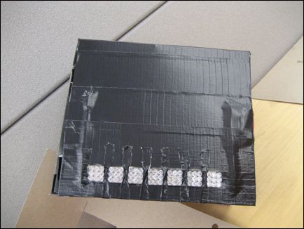
The major hardware components were the 63 Ultra Red 1000mcd 5mm LEDs. These 1-inch LEDs have a water clear epoxy. The maximum forward current is 20mA, with a maximum forward drop of 2.0 V and maximum reverse voltage of 5 V. All these were soldered to the large bread board, by arranging them by 9 LEDs (3 rows, 3 columns) per key. To limit the current through the LEDs a 10 ohm resistor was used for the 8 non sensor LEDs in each key, and a 330 ohm resistor was used for the sensor LED. The rims of the LEDs were trimmed using the Dremel tool to remove the flange to get the LEDs to fit closer together.
One thing that we tried and did not work was to use the oscilloscope while testing. This was because the scope loaded the LEDs too much and corrupted their discharge time, so the device would not operate properly.
Two LM317TFS Voltage Regulators were used, which are capable of supplying 1.5 A of current, with an adjustable output voltage from 1.2V to 37V. They were configured to output approximately 3.2 V for the LEDs.
One regulator was used for 4 keys, while the other was used for the other 3. A small piece of aluminum sheeting was used to make a heat sink for each of them, and a fan was used to keep these regulators cool, as seen in the picture below.
Parts List:
| Part | Quantity | Price |
| LEDs | 100 | $14 |
| Resistors (309 ohms) | 7 | Free |
| Resistors (10 Kohms) | 7 | Free |
| Large bread board | 1 | Free (Surplus) |
| Small bread board | 1 | $1 |
| ATMega664 | 1 | $8 |
| Fan | 1 | $1 |
| Regulators (LM317TFS) | 2 | Free (Surplus) |
| Protoboard | 1 | $4 |
| Audio Amplifier (LM386) | 1 | Free (Surplus) |
| Total | $ 28 |
For more detail: LED Sensor Piano Keyboard Using atmega644