Hi this Instructables is designed to give you a way to protect your LinkIt ONE while you are using it.
Let me first say that their are a couple of enclosures available, one of which is on thingiverse, however I was unable to find a model of the board itself anywhere. Saying this in sure someone will let me know a location in the comments section. Thanks in advance.
The sketch up model I created has been uploaded to the 3D warehouse and I will include a link in the next section.
If all this sounds interesting please read on, if not then thanks for reading to this point.
Step 1: Create the LinkIt One Board

The model of the board was fairly simple to create, I used Sketch up to lay out the components, placing each type on a layer so that parts could be hidden as needed during the modeling.
As I later wanted to use the model to design the enclosure, it had to be accurate so I used a set of digital calipers to measure each piece and to lay it out on the base board. The most important piece to get right was the base board and the holes that are normally used to position a board with posts.
I have uploaded my model to the 3D warehouse and you are free to download it for use in your own projects.
Step 2: Sketch Up the Base
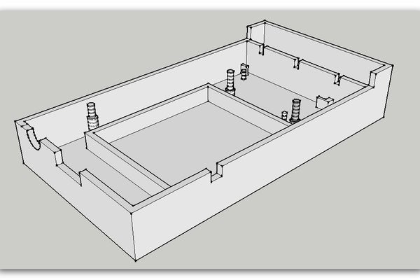
For the base the first thing to do was to ensure that the LinkIt One boardand all of its components where grouped together so that they could not become attached to any section of the enclosure, also to place that group on a new layer to allow it to be hidden when needed.
With that done I started with the base laying out the bottom, making it larger than the board and including space for a wall around the board. The base has a number of structures designed to hold different accessories that come with the board.
- Posts – these are to be used to support the board and hold it in place. These where laid out using the sketchup board model I made earlier I simply recreated the circle on the board and because the board was grouped the new circle did not lock to it. I then hid the board layer and extended the circle into the box model.
- Additional posts where added to hold the GSM antenna and were added by direct measurement of the part itself.
- The Battery compartment – this is a simple wall designed to just hold the battery, it has a break in the wall which allows the wires to reach the board.
- WiFi antenna slots – if you look to the far end of the box you will see two lugs these are just large enough to slot the aerial into.
- The next addition is the slot box at the far end – this is to locate the GPS aerial it simply sits in the slot with the wire passing through one of the notches which also allow you to put the aerials on the outside of the enclosure if needed.
- Around the sides of the box are more notches these allow for the wires needed to connect the LinkIt One to the computer etc, as well as to reset the board without having to open it up
Omission
I decided to leave out a slot for the SD card and Sim card for the following reasons
- If a card is needed it is not something that will be removed and so opening the box up is not such a big thing.
- the SIM slot is sideways on the board making the distance to insert it too large and more likely that trying to would result in the SIM dropping into the enclosure.
- SD card is on the end of the board but the same reason as for the SIM was applied.
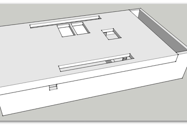
Step 3: Sketch Up the Lid
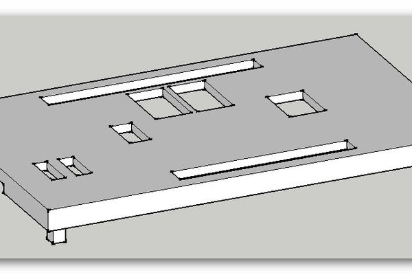
The lid has four posts (one at each corner) these are used to locate the lid onto the enclosure, but will also keep it locked in place. The holes you can see in the top where all added by direct measurement of the board and allow access to the pins and connections of the board. The holes I put in to all you to get to the switches where and after thought, but I think quite important.
Step 4: Prep Files for Printing the Finished Housing
The first image in this section shows the completed enclosure, to print the two parts of the box you need to export them to STL files – (search the add in warehouse for STL and install that into your Sketchup setup.)
The first task is to use a tool called solid inspector (again from the warehouse) select each part to be printed – run the tool it will identify errors in your model and you have the option to fix them prior to printing. Now decide which part you want to export first then hid the other (as well as hidding the board model) I did the base first as it was in the right orientation – go to the file menu ad select export STL – set the options to ASCII and units mm.
Now for the lid – un-hide every thing then hide the board and the base, now select the lid and then the move tool. Then rotate the lid so that the top of the lid is face down – the reason for this is so that it prints better and you will not need to include support structures in the print job. now follow the same steps to export the part to a new file.
link to the Sketchup File on the 3D warehouse this will allow you to modify the model to your needs prior to printing, the two attached files are my exported STL files.
Step 5: Preparing the Printed Parts
Once printed don’t expect to fit all the parts of the board in straight away, you will need to tidy up the stray threads of plastic, for this I used a sharp knife. The sandpaper is used to smooth out some of the connections and posts.
TOP TIP
When you layout your sketchup model and size all the parts to be printed – make then about 0.25 mm smaller this should allow for spread of the plastic during heating and hopefully reduce the amount of smoothing you will need to do.
Be careful when trimming parts – I accidentally removed one of the Board pins, but luckily two where sufficient for the job.
You will also need to use a tool of some form (I used a small screwdriver) to pierce the label on the back of the LinkIt One board its covering the hole for one of the posts.
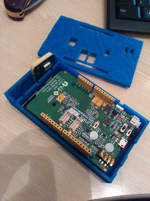
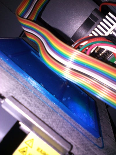
Step 6: Put It All Together

I think the pictures say it all really. Slot the battery into the walled off ares in the base, then drop the aerials into their respective locations. With all of the parts in place attach the wires for the aerials to the development board and start to lower it onto its pins, before it goes all the way down plug the battery into its socket and finish putting the board in place, taking care to push the battery wires under the board.
This is another reason why there is no slot for SD or SIM cards – the battery wires get in the way.
The last images show the enclosure all ready for use.
Thanks for reading
Source: LinkIt One – 3d Printed Case