We recently obtained a clock that flew on a Soyuz space mission.1 The clock, manufactured in 1984, contains over 100 integrated circuits on ten circuit boards. Why is the clock so complicated? In this blog post, I examine the clock’s circuitry and explain why so many chips were needed. The clock also provides a glimpse into the little-known world of Soviet aerospace electronics and how it compares to American technology.
The Soyuz series of spacecraft was designed for the Soviet space program as part of the race to the Moon. Soyuz first flew in 1966 and has made more than 140 flights over the past 50 years. The spacecraft (below) consists of three parts. The round section on the left is the orbital or habitation module, holding cargo, equipment, and living space. The descent module in the middle is the only part that returns to Earth; the astronauts are seated in the descent module during launch and reentry. Finally, the service module on the right has the main engine, solar panels, and other systems.
The descent module contains the spacecraft’s control panel (below).2 Note the digital clock in the upper left. Early Soyuz spacecraft used an analog clock, but from 1996 to 2002, the spacecraft used a digital clock.3 The digital clock was also used in the Mir space station. The clock was eliminated from later Soyuz spacecraft, which used two computer screens on the control panel in place of the earlier controls.
A closer look at the clock
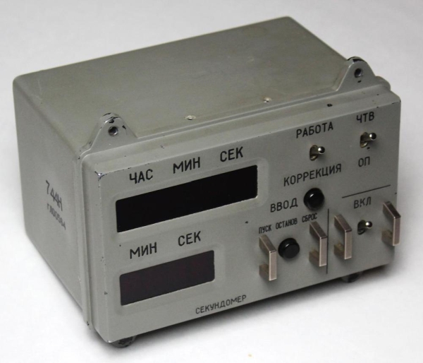
The diagram below shows the clock’s labels translated into English. The clock has three functions: the time, an alarm, and a stopwatch. The “Clock of Current Time”5 mode shows the current Moscow time on the six upper LED digits, while “Announcement” shows the alarm time. The alarm can be set to a particular time; at that time, the clock triggers a relay activating an external circuit in the spacecraft.4 The clock is set using the “Correction” mode; digits are incremented using the “Enter” button. The lower half of the unit is the stopwatch; the bottom four LEDs display elapsed minutes and seconds. The lower pushbutton stops, starts, or resets the stopwatch.6 Finally, the power switch at the right turns the clock on.
We wanted to see what was inside the clock, of course, so Marc unscrewed the cover and removed it from the clock. This revealed a dense stack of circuit boards inside. The clock was much more complex than I expected, with ten circuit boards crammed full of surface-mount ICs and other components. The components are mounted on two-layer printed-circuit boards, a common construction technique. The boards use a mixture of through-hole components and surface-mount components. That is, components such as resistors and capacitors were mounted by inserting their leads through holes in the boards. The surface-mount integrated circuits, on the other hand, were soldered to pads on top of the board. This is more advanced than 1984-era American consumer electronics, which typically used larger through-hole integrated circuits and didn’t move to surface-mount ICs until the late 1980s. (American aerospace computers, in contrast, had used surface-mount ICs since the 1960s.)
One interesting feature of the clock is that the boards are connected by individual wires that are bundled into wiring harnesses (below). (I expected the boards to plug into a backplane, or be connected by ribbon cables.) The boards have rows of pins along the sides, with wires soldered to these pins. These wires were gathered into bundles, wrapped in plastic, and then carefully laced into wiring harnesses that were tied to the boards.
Read more: INSIDE THE DIGITAL CLOCK FROM A SOYUZ SPACECRAFT