Summary of Micro Controller Programming: Making a Set of Traffic Lights
This tutorial guides users in building a Pelican crossing traffic light system using an ATtiny2313 microcontroller. It assumes prior knowledge from a previous "Ghetto Programming" guide and details the assembly process, including wiring components on a breadboard, connecting a parallel port for programming, and installing LEDs, a buzzer, and a push button. The article concludes by explaining how to customize code preferences for timing, light oscillation, and sound settings.
Parts used in the Pelican Crossing Traffic Light System:
- 1x ATTiny2313-20PU
- 1x 20 pin socket
- 1x Parallel port plug
- 1x Breadboard
- 1x Jumper Links
- 2x Red Led's
- 1x Orange (not amber) Led
- 2x Green Led's
- 1x White Led
- 1x Electronic Buzzer
- 1x Push to make button
- 3x 1K Resistors
- 6x 150ohm Resistors
- 5x Head Plug
- 2x Head Socket
- 1x Battery Box
- Wire
- Solder
So you wana learn how to programme a micro controller?
This tutorial has been designed as a next step, following the fantastic tutorial ‘Ghetto Programming: Getting started with AVR microprocessor on the cheap.’ by The Real Elliot link you should read this before progressing onto this next step.
Today my friends we are going to make a pelican crossing using an Ateml ATTiny2313. This is probably more common in the UK but a pelican crossing allows pedestrians to stop road traffic and cross in a safe manner.
At the end of this project you might like to mess about with the code and get the lights to sequence for your countries equivalent system, or for a junction like a cross roads (intersection).
Step 1: Parts
Ok if you are continuing this project after completing the Ghetto Programming instructable you will need to order a few extra parts. I have a list below which will detail every thing you need for this project. However if you already have the parts (Micro controller, LEDs etc..) then just leave these out. For clarity I have given the part numbers which you can use to order them directly from Rapid Online the company from which I ordered mine.
These are minimum requirements you could order more for backup or expansion of this project.
- 1x ATTiny2313-20PU (73-4316)
- 1x 20 pin socket (22-0170)
- 1x Parallel port plug (15-0510)
- 1x Breadboard (34-0655)
- 1x Jumper Links (34-0495)
- 2x Red Led’s (55-0155)
- 1x Orange (not amber) Led (55-0124)
- 2x Green Led’s (55-0120)
- 1x White Led *(55-1640)
- 1x Electronic Buzzer (35-0072)
- 1x Push to make button (78-0350)
- 3x 1K Resistors (62-0370)
- 6x 150ohm Resistors (62-0350)
- 5x Head Plug (22-0515)
- 2x Head Socket (22-5114)
- 1x Battery Box (18-3685)
Rapid Online
In total this came to £17.18 ex vat (approx $35.42) however you might find it cheaper else where but I doubt it.
Rapid Online offers free shipping when you spend over £5 it might be worth looking about for a few goodies and upping the led’s and chips for backup if you intend to explore microchip programming further.
As well as the above parts you will need some basic stuff which you may already have…
Wire (probably about 0.5mm stranded wire)
Solder (around 22swg lead free stuff)
You will also need these tools…
Soldering Iron + Stand + Sponge
Solder Sucker/Pump
Side Cutters
Wire Strippers
Once you have all the parts you are ready to assemble your project.
Step 2: Getting Started
I am going to assume you already have the programming cable and software setup from the Ghetto project and jump straight into building the project.
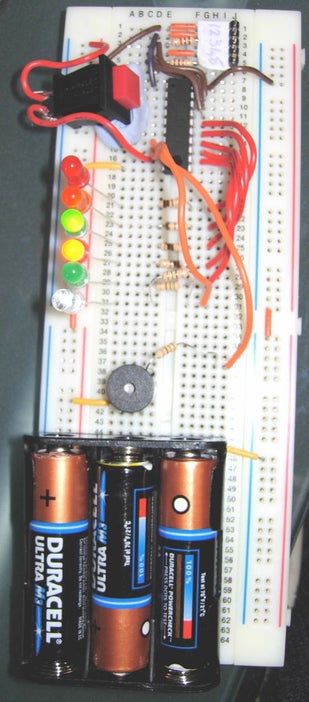
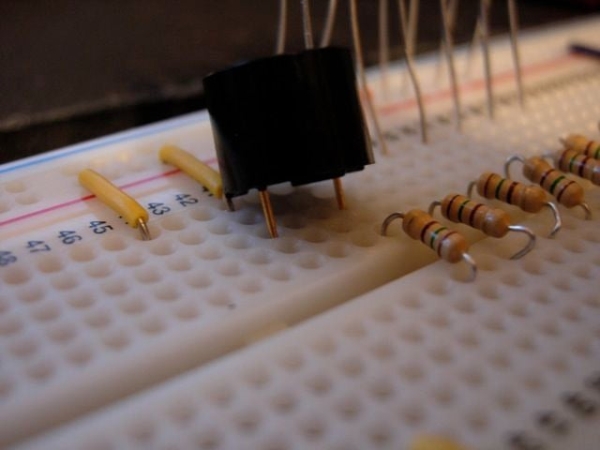
Ok first we are going to lay a few things out connect the pins of the battery the the +ve and -ve lines, plug in the micro controller and the head pins.
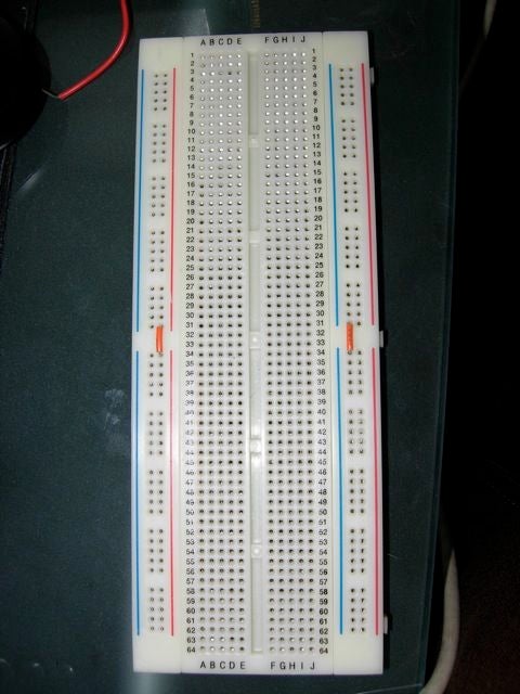
To start with you will notice that there are 2 sets of holes running down both sides of the board each row down is interconnected up to the break in the middle of the board, effectively there are 8 strips running down the board. We are only going to use the inner 4 strips on the board. To make the top strips link with the bottom ones we need to connect them using a jumper wire. You can see the orange wires on the image below they are joining the top and bottom.
Now place the battery on the board at the bottom as close to the edge as possible and work out where its pins will rest, ensure the +ve and -ve pins are on different sides of the central divide. Using the a longer jump wire connect the pins to the +ve and -ve strips. (Notice the yellow jump wires in the image below). They are connected because the rows are connected across up to the central divide (this is different to the way the power strips work which are columns not rows).
Ok Now at the very top right of the board push the header pins into the board it should use rows 1-5 then two rows down (8) insert the microchip so it bridges the gap over the centre.
Ensure the micro controller is inserted correctly (the dip/cut semi circle should be nearest pin 8 on the breadboard).
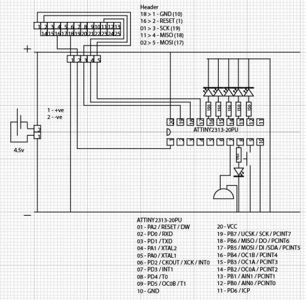
Step 3: Wiring Up the Micro Controller
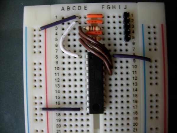
I used my own wiring for the header pin so make sure you connect your parallel port pins to the right place on the micro controller. (Just follow the instructions on the Ghetto project).
Once its wired up you should have some thing like this… If you do not already have 1k resistors on your programming cable ensure they are installed on your board to protect the parallel port on your computer from being fried.
Step 4: Installing the LEDs
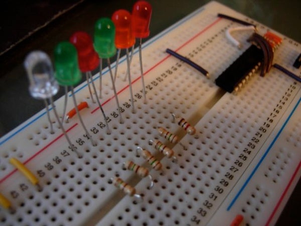
Before we begin ensure all LEDs are connected the right way around. The short lead goes into the -ve supply the long one goes into the micro controller (+ve).
Also ensure you use the 150ohm resistors on the LEDs lay them out as below.
I have jumped the centre divide with resistors and put the -ve pin directly into the -ve rail so that I create a circuit, you could alternatively solder the resistor onto the long wire coming out of the LED.
Step 5: Buzz
Ok in the same way that you connected the LED’s add the buzzer you don’t need a resistor however if you find the noise annoying a 150ohm resistor will reduce the volume a bit.
Step 6: Inputs and Outputs
Step 7: Home Run
Now you have it all wired up, if your microchip is still programmed from the LED flashing Ghetto project you will probably notice that the white wait LED is flashing on and off. This means its all working.
Ok next step assumes you already know how to program it from the Ghetto project.
The code below is clearly commented and there are options which I will go through in the next step. For now just load up the code and press the button!
Step 8: Preferences
In the code you have just programmed will make the lights changing very quickly but there are a set of options at the top of the file which you can edit to your own preferences.
Here is what each one does…
#define PWRSTTIME 1
In the case that power is lost the the traffic lights it makes sence for the lights to stop all traffic in case of confusion whilst a pedestrian is crossing. This preference allows you to set how long the lights stay red for before sequencing to green. (This example shows 1 second)
#define WAITTIME 1
This is the amount of time the traffic lights will wait after the button is pressed before sequencing to red. (This exampe shows 1 second)
#define CROSSTIME 1
This is the amount of time the lights will stay red to let pedestrians cross before sequencing back to green. (This example shows 1 second)
#define BEEPON 1
This states whether the beeper should sound of not 1 is on 0 is off. (It can be annoying to you and others to have this set to 1 when testing)
#define BEEPOSC 1
This defines whether the beeper should oscillate on and off. 1 is on and 0 is off.
#define AMBEROSC 1
This defines whether the amber light should oscillate on red & amber. 1 is on and 0 is always on.
#define REDONOSC 1
This defines whether the red light should be on whilst the amber light is oscilating. 1 is on 0 is off.
#define AMBEROSCNO 2
This sets how many times the amber light should oscillate. This example shows 2 oscillations (on, off, on off)
#define WALKOSC 1
This defines whether the walk light should oscillate on red & amber. 1 is on and 0 is always on.
#define WALKOSCNO 2
This sets how many times the walk light should oscillate. This example shows 2 oscillations (on, off, on, off)
Step 9: And They All Lived Happily Ever After… the End.
Ok well thats it if you want to learn more about the code read through and you will notice the ‘//’ this indicates a comment and I have used these comments to explain what is going on.
However if you need more help or guidance I have a few links and resources below…
Before I go I would like to thank The Real Elliot for his Ghetto Programming tutorial which is what inspired me to create this project. Micah Carrick for his tutorials which helped me learn how to read inputs and thanks to you for reading this tutorial. The AVR Freaks community who helped me in the planning of this project you were a really big help. My friend Tom P who answered a few questions and also finally Paul who taught me electronics at Court More Secondary when I was young.
Links & Resources
AVR-LibC – This is the AVR-LibC programming language guide
ATTiny2313 PDF – This is the PDF documentation for the ATTiny2313 microcontroller which is used in this. It has a good pin out diagram.
Rapid Online – UK Retailer for the parts I used today
Digikey – US Retailer for the parts I used today
Electronics Information – Electronics information for beginners this site is amazing a great place to look for information about soldering, electronic components, resistor colour codes etc…
AVR Freaks – AVR Freaks is a great web community for AVR micro controller stuff.
Thanks for reading, and have fun!
Source: Micro Controller Programming: Making a Set of Traffic Lights
- What is the primary purpose of this project?
The project creates a pelican crossing that allows pedestrians to stop road traffic and cross safely. - Can I modify the code for different countries or junction types?
Yes, you can mess about with the code to sequence lights for your country's equivalent system or a junction like a cross roads. - How do I connect the battery pins on the breadboard?
You must ensure the +ve and -ve pins are on different sides of the central divide and connect them to the respective strips using longer jump wires. - Which way should the LED leads be connected?
The short lead goes into the -ve supply and the long one goes into the micro controller (+ve). - Do I need a resistor for the electronic buzzer?
No, you do not need a resistor, but adding a 150ohm resistor will reduce the volume if the noise is annoying. - What does the PWRSTTIME setting control in the code?
This preference sets how long the lights stay red after power is lost before sequencing to green. - How can I change the number of times the amber light oscillates?
You edit the AMBEROSCNO value in the code to set the specific number of oscillations. - Is it possible to turn off the beeper during testing?
Yes, setting BEEPON to 0 turns the beeper off to avoid annoyance while testing. - What indicates that the microchip is working correctly?
If the white wait LED is flashing on and off, it means the system is all working. - Where can I find documentation for the ATTiny2313 microcontroller?
A PDF documentation with a good pin out diagram is available via the provided link for the ATTiny2313.