Summary of Micro:bit Compass
This article guides users in building a simple digital compass using a micro:bit. It covers hardware requirements, including optional components for portability and aesthetics, explains the underlying magnetic sensor technology and LED matrix output, details angle mapping logic, and provides resources for coding via MakeCode and calibrating the device.
Parts used in the Digital Compass:
- Micro:bit
- Battery Holder (3V with JST connector)
- CR2032 battery or 2 x AAA/AA batteries
- 3D Printed Cover
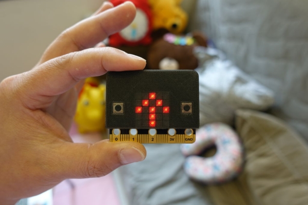
This instructables show how to use micro:bit to make a simple digital compass.
Step 1: Get a Micro:bit
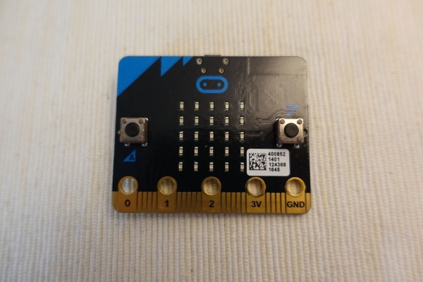
If you not yet have a micro:bit, you may get a micro:bit here: https://microbit.org/resellers/
Step 2: Optional: Battery Holder
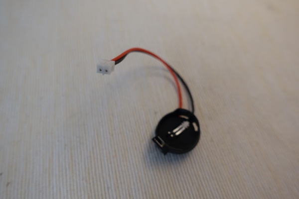
If you want to make the digital compass portable, you may consider get a battery holder.
Any 3V battery holder with JST connector should be ok. The battery can be CR2032, 2 x AAA batteries, 2 x AA batteries, etc.
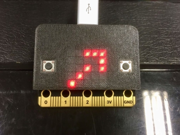
Step 3: Optional: 3D Printed Cover
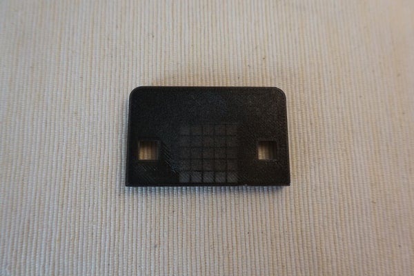
I feel direct view the SMD LED light is not so comfort, so I have made a 3D printed cover diffuse the light and make every LED like a perfect square pixel :>
If you also like the pixels, you can download and print the cover here:
https://www.thingiverse.com/thing:3511591
Step 4: How Does Digital Compass Work?
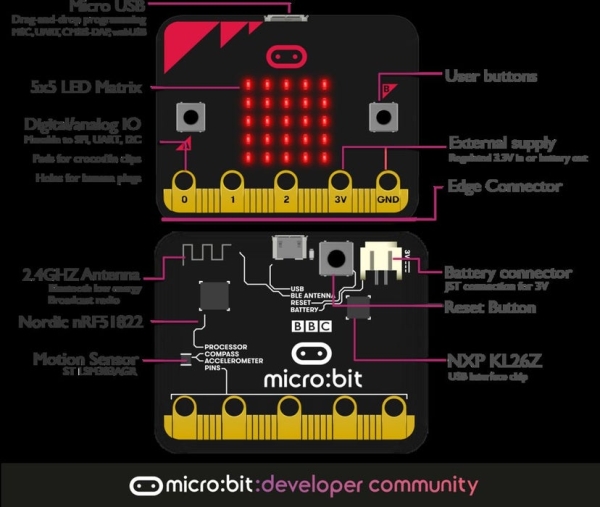
Input
micro:bit have a magnetic field sensor, just like a normal compass needle, it can sense the magnetic field produced inside Earth. micro:bit library translate the field value into 360 degrees relative to north.
Output
micro:bit have 5 x 5 LED matrix, it is good enough to show an arrow in 8 directions. (North, NE, East, SE, South, SW, West, NW)
Ref.: https://tech.microbit.org/hardware/
Step 5: Note on the Magnetic Field Direction
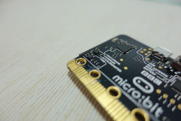
Please reminded that the magnetic field sensor and the LED are placed on different side of the PCB. So when you look at the LED side the magnetic field reading is flipped. Or you can treat the reading is counter-clockwise start from North.
Step 6: Angle Mapping
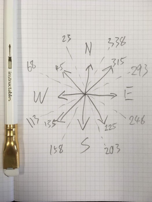
The input is a 360 degrees value and the output is 8 directions arrow, here is the angle mapping:
 23 -  68 NW
 68 - 113 West
113 - 158 SW
158 - 203 South
203 - 248 SE
248 - 293 East
293 - 338 NE
Others    North
Step 7: MakeCode
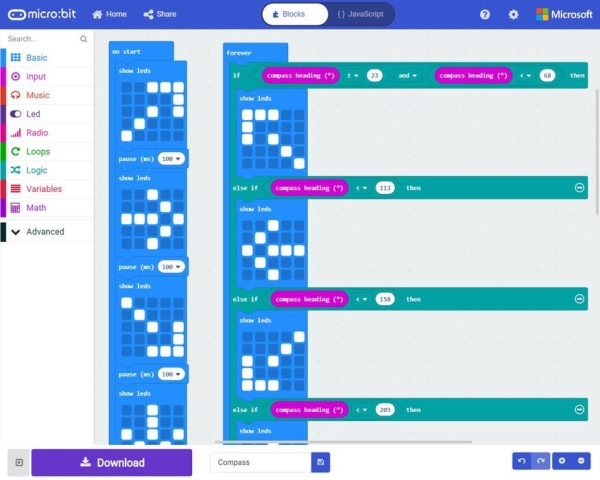
Here is my sample block code:
Simply download and copy to micro:bit drive to run.
If you are not yet familiar with using micro:bit please read the official quick start guide first:
https://microbit.org/guide/quick/
Step 8: Calibrating the Micro:bit Compass
If you are first time using the micro:bit magnetic field sensor, the LED matrix will scroll the words TILT TO FILL SCREEN.
Please follow the support page video to calibrating the micro:bit compass:
https://support.microbit.org/support/solutions/art…
Step 9: Happing Coding!
micro:bit compass is just a very simple example, micro:bit have much more can be done.
Let’s explore more ideas here:
Source:
- How does the micro:bit detect direction?
The micro:bit uses a magnetic field sensor that senses Earth's magnetic field and translates the value into 360 degrees relative to north. - What output display is used for the compass?
A 5 x 5 LED matrix is used to show an arrow indicating one of eight directions. - Can I make the compass portable?
Yes, by adding an optional 3V battery holder with a JST connector. - Why was a 3D printed cover created?
The cover diffuses the SMD LED light to make every pixel look like a perfect square and is more comfortable to view. - Is the magnetic field reading flipped on the LED side?
Yes, because the sensor and LED are on different sides of the PCB, the reading appears flipped or counter-clockwise from North when viewing the LEDs. - What happens if the screen says TILT TO FILL SCREEN?
This indicates you need to calibrate the micro:bit magnetic field sensor by following the support video guide. - Where can I find the sample code?
The sample block code is available at the provided MakeCode link for download. - How many directions can the compass display?
The compass displays eight directions: North, NE, East, SE, South, SW, West, and NW.