Okay, I admit I don’t have a monkey. But would you be looking at this if I didn’t mention monkey? And this would work for a monkey.
Does your monkey or dog wander off? Would you like to see where he/she is? Well, they make dog trackers (see picture). However, most are over $100 and require a monthly tracking service fee.
So this Lazy Old Geek (L.O.G.) decided to make my own. This requires a collar module (see picture) and a display module (see picture).
HowItWorks: The collar module is battery-powered based on Arduino, has a GPS module and an nrf24L01+ transceiver to talk to the display module. The display module is battery-powered based on Arduino, has a GPS module and an nrf24L01+ transceiver to talk to the collar. It also has a compass module and an LCD display. The collar transmits its GPS coordinates and battery voltage to the display. The display module calculates its own GPS coordinates and calculates the distance and direction between the two. The LCD shows which direction the collar is and the distance between the two.
Step 1: Collar Module
What It Does: The GPS calculates the location of itself and sends it to its Arduino. The Arduino sends this information along with the battery voltage to the nrf24L01+ module which broadcasts it wirelessly (to the display module).
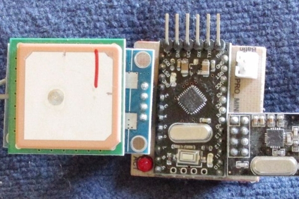
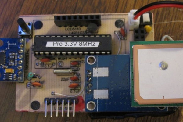
The collar module consists of four major components:
A Ublox NEO-6M GPS (see picture)
An 8MHz 3.3V Arduino Pro Mini (see picture)
An nrf24L01+ wireless transceiver (see picture)
A Lithium battery (see pictures)
There’s also a custom made PCB, an LED, some connectors.
For my battery-powered Arduino projects, I’m standardizing on JST2.0 2 pin connectors for power. The four main components can be bought on ebay for a good price.
I wrote an Instructable on setting up the Ublox NEO-6M GPS:
https://www.instructables.com/id/Arduino-Ublox-GPS/
This Instructable shows how to convert an inexpensive Arduino Pro Mini (16MHz, 5V) to an 8MHz 3.3V Arduino Pro Mini:
https://www.instructables.com/id/Arduino-33V/
And I wrote an Instructable on using the nrf24L01+ transceiver:
https://www.instructables.com/id/LOG-Wireless-Temperature-Monitoring/
For the battery, I selected a 3.7Vdc Lithium Ion battery also bought on ebay. This is a common size for replacement batteries for some smartphones and tablets. These come in various sizes and capacities. I had to solder a JST2.0 connector to the batteries. I hadn’t really decided on which one to use.
I also purchased a USB Li Ion 1A battery charger and added a JST2.0 connector to charge these batteries (see picture).
Warning: The standard USB port on a computer will often only put out 0.5A. While this will work, it will take longer. The charging will be faster if a 1 or 2A source is available, such as a USB 2A AC adapter.
I designed the PCB to connect the components. (see schematic) R1 and R2 form a voltage divider to monitor the battery voltage.
Technobabble: The technically inclined may notice that there is no voltage regulator in this design. While Li Ion batteries are nominally rated at 3.7Vdc, depending on the charge they will actually vary from about 4.2Vdc down to about 3.0Vdc. This Arduino Pro should operate from 1.8 to 6Vdc. The nrf24L01 from 1.9V to 3.6V. And the Ublox neo-6M 3V to 5V. So everything should work down to about 3V which is probably limit I want to discharge Li-ion battery.
Eagle cadsoft files for both the collar(PetTrackee) and the base(PetTrackerBase) are attached.
Step 2: Display Module
What It Does: The nrf24L01+ receives the GPS and battery voltage from the collar module.
The internal GPS calculates the location of itself. The Arduino calculates the distance and direction between the two GPSs. The LSM303DLHC magnetometer is an electronic compass. It is used to find out where North is so that the display will point towards the collar module. The distance will also be displayed.
The display module consists of several major components:
A Ublox NEO-6M GPS
An nrf24L01+ wireless transceiver
An LSM303DLHC magnetometer (3.3Vdc)
An LCD5110 display (3.3Vdc)
A custom Arduino PCB
A Lithium battery (see pictures under collar module step)
Arduino PCB schematic is attached. Power is regulated with a 3.3Vdc regulator. U$1 is a pushbutton on/off switch:
S1 is a pushbutton not needed in this application.
Buz1,2 are pads for a buzzer, not implemented.
There is a USB-BUB type connector for loading Arduino sketches.
The Eagle Cadsoft files are included in the collar module step.
The two pictures with displays shows an ‘arrow’ pointing in the direction of the collar and the distance to it.
Source: MonkeyDogTracker