Introduction
For our ECE 4760 Final Project, we use an infrared LED and phototransistor armband to detect muscle inflections in arm and wrist movement which are used to manipulate the volume and speed of pre recorded songs. By pumping your fist, you will change the speed at which the song is playing. Isolated wrist movements correspond to volume changes. By moving your hand towards your body in an upward motion, you increase the volume. By moving your hand towards the ground in a downwards motion, you decrease the volume. Other similar motions that provide similar phototransistor outputs can be used to control volume as well. We use a signal peak and fall detection system to control sound. A push button is used to rotate between three Michael Jackson classic songs. We use the UART to display initial directions and other messages to the user to aid in the users activity. We both enjoy various types of music and thought manipulating sound based on muscle movements would be interesting and could lead to other practical applications.
High Level Design
Motivation and Rationale
Both team member are large fans of music, so music became the main focus and drive for the final project. We had various ideas of how to produce or manipulate sound. We decided to use the detected light reflected from IR LEDs against muscles in the arm to manipulate various aspects of songs. Later, we chose to program Michael Jackson classic songs with the hopes to appeal to a large audience of very taste of music and various age groups. The songs were catchy, fit the beat timing requirements, and recognizable within the first few notes.
The system is highly usable by all age groups, requiring very minimal training. The system has preset thresholds to determine the level and location of muscular activity. Furthermore, we expect that this method of playing electronic music is highly conducive to users with special needs. The LEDS and phototransistors may be placed on any body part which the user is able to control. As a result, a user who cannot use his or her hands to play music, as is often required for musical instruments, may use this device to manipulate a song or other useful things by moving a muscle group.
Our original proposal was to build an infrared LED and phototransistor armband that will detect muscle inflections of finger movement. With the Phototransistor output, we hoped to imitate a small piano with various notes corresponding to the movement of specific fingers. Using the LCD, we wanted to display initial directions and other messages to the user to aid in the users activity. Also, the musical key would be user specified using the keypad. Throughout testing we determined that we were not about to specify individual finger movements, thus we focus on larger muscle groups. Our project has morphed throughout the design process based on our results from testing, feasibility, and our interests.
Logical Structure
Our main hardware consist of an armband with 4 LEDs and 2 phototransistors outputted to a filtering system and then feed into the ADC. There are two main parts to our software; the time sensitive interrupt, and the less time-sensitive functions. In the time-sensitive interrupt collect ADC samples from sensor, detect peaks and falls from the ADC samples, and output the sound. In the less time-sensitive Main functions, we update song and frequency changes and perform data processing in order to manipulate sound.
Mathematical Background
In this project, software peak detection is applied to amplified phototransistor signals by checking for a specific amplitude and direction of change relative to a baseline value. Both of these elements are essential for correct peak detection. For example, when detecting a signal rise above threshold, an above-threshold value and a simple threshold crossing are not enough to show that the condition has occurred because the signal must also be increasing. All of these necessary conditions hold specifically when one sample of a signal is below the set threshold and the next sample is above it. Correct implementation of this peak detection is included based upon code suggested in an earlier ECE 4760 lab and is described by the code below.

The method of sound synthesis used in this project was based upon a common model of FM sound synthesis to create tones similar to those produced by musical instruments. Essentially, the phase of a sine wave is varied according to a second sine frequency of some scaled amplitude and the resulting phase-modulated sine is amplitude-scaled so that the tone appears to grow and decay, as shown in the following equations:


This method is highly useful to digitally synthesize sounds in an easily codable and understandable way while producing complex and realistic sounds. Low FM frequencies (denoted by (omega)2) produce sine wave segments with slightly varying frequency and little other distortion, but as FM frequency increases, the waveforms become increasingly distorted and appear inherently different from a sine wave. This project ultimately did not include the sine-varying phase term that creates FM synthesis in order to preserve simplicity, resulting in sound synthesis governed by the equation below.

This equation essentially models an instrument that produces a waveform with little distortion, such as a bell or chime.
Hardware/Software Tradeoffs
The project’s most important tradeoffs between software and hardware design are in conversion between digital and analog signals. These concerns include filtering of the phototransistor signals (A/D conversion) and conversion of digital waveform calculations to smooth sine-wave analog output (D/A conversion). Both of these functions were implemented using hardware more than software; we generally avoided making the software unnecessarily complex in order to conserve memory and execution time of the MCU since our code stores several long floating-point vectors and performs two complex functions. Filtering of the sensor signal inputs was performed completely in hardware, though there are many digital signal processing algorithms which could serve the same function. Conversion from digital to analog sine output was also performed completely in hardware using the DAC chip, but software could have been used to convert this signal to a single PWM voltage output and, with fast enough timing, even low-pass filter that output to be a fairly smooth sine wave. The one ambivalent function performed in software rather than hardware is peak detection, which could have been implemented using a simple op amp circuit.
Hardware Design and Implementation
IR LED and Phototransistor Armband
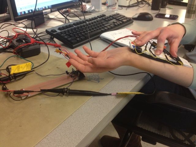
We built an armband with integrated infrared LEDs and phototransistors. The final armband has two phototransistors with an LED to the right and left of the phototransistor. The armband will be vertically positioned on the arm so that it can detect the muscle inflections on commonly used muscles for gripping and lifting. The infrared LED will illuminate the muscle and the light reflected from the muscle will be detected using the phototransistors. We are able to isolate the various phototransistor outputs to detect which muscle is being moved and causing the greatest output. The design of the armband is based on a 1’ 7/16 inch width, 6’ ¾ inch length , and ¼ inch thick piece of cardboard. The LEDs and phototransistors are placed in sequence along the middle of the cardboard, 3/4’ from the top of the board. The LEDs and phototransistors were placed through the cardboard. All LED hot leads were connected to individual red wires. All phototransistor hot leads were connected to individual orange wires. LED and phototransistor ground leads are all connected with one yellow ground wire. Heat shrinks were placed on all connections to prevent shortages. After building our first main sensor armband, we acquired black foam. We a large block of black foam with a butter knife to the shape of the cardboard a couple of centimeters in thickness. We cut small holes through the black foam just large enough for the LED and phototransistor heads and laid the foam along the cardboard. The black foam is used instead of tape to block out light.
The ends of the sensor are numbered 1 and 2 in order to determine thecorrect direction to place the sensor along the user’s arm. The sensor closest to end 1 is routed to Port A1 (ADC channel 1) and senses muscle movements close to the wrist, while the sensor closer to end 2 is routed to Port A2 (ADC channel 2) and is placed closer to the center of the forearm, sensing large-scale arm movements. The first channel sensor can sense fine movements, especially in the wrist and hand, while movements in the second channel tend to produce much smaller signals and only capture large whole-scale arm movements. These differences are partly compensated by having the sensor band use a phototransistor experimentally found to be more sensitive as the mid-forearm sensor. These signal differences are also accounted for in detection software by choosing detection thresholds according to the different levels expected for each sensor channel.
Note: For LED and Phototransistor Circuit Schematic, See Appendix
| Arm Band Parts |
| R5 = R6= R7 = R8 = 100 |
| R9= R10 = 20k |
| LTE4208 (quantity = 4, LEDs) |
| LTR4206 (quantity = 2, Phototransistors) |
Audio Amp Driver
A audio buffer circuit is used to drive two Logitech S-120 speakers designed for computers. The circuit uses the Sallen-Key topology in a common configuration which acts as a unity-gain amplifier in order to provide powered audio output to the speakers based on the DAC waveform, which is driven by the low-power microcontroller and is not conducive to the high-power consumption needed for speakers. The MCU output waveform has a voltage range (0V-5V) high enough that no additional voltage level amplification is needed.
For a full schematic diagram of the audio driver amplifier, please refer to Appendix.
Additionally, this amplifier configuration serves as a slight low-pass filter. The time constant and cut-off frequency cut-off frequency are calculated using published equations (source) and are found to be: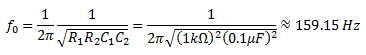
This cut-off frequency is similar to many of the audio frequencies played. Therefore, the use of this filter and buffer may attenuate the signal by several decibels, but and its use will help to meet speaker power requirements.
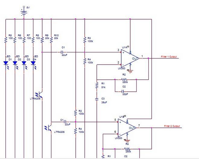
Filters System A dual filter and amplifier unit was designed to process signals from each phototransistor sensor in hardware before routing the signal to software. One filter subsystem acts upon the output of each, using a LF353N op amp to translate the sensor signal to an output of greatly increased amplitude and maximal swing. Firstly, it removes DC offset by placing a large capacitor C1 on the input branch and fixing the end ofthis capacitor input to a voltage divider of equal resistance between 0V ground and MCU Vcc=5V so that the input signal is centered in the output voltage range of the amplifier. The signal at the middle of the divider is then routed to the non-inverting input of an op amp. Values for the voltage divider resistors were made as large as possible, but their size was limited by their contribution to the input time constant, which must be small enough to allow passage of movement-generated signals, which may be as fast as 0.1 s. Using final component values, this input circuit effectively creates a high-pass filter with a time constant of: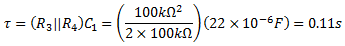
This value is large enough to admit all relevant signals on the time scale of human arm movement and small enough to remove meaningless DC offset and slow amplitude variations. In the feedback and filtering networks discussed below, a capacitor is connected between an inverting input resistor and ground, giving the circuit unity gain for DC components onthe non-inverting input. The output then has a filtered and greatly amplified reflection of the small AC component at the input while keeping the same desirable DC value seen at the input. The exact gain applied to the is not known and is notgiven in the LF353N datasheet, but it generally produces AC sensor signals around 0.5V to 2V in amplitude and is deemed acceptable for these inputs
Parts List:
| Description | Quantity | Unit Price | Item Total | Necessity | Comment |
| Computer speakers | 1 set | $9 | $9 | Main project | Source: http://www.newegg.com/Product/Product.aspx?Item=N82E16836121016 |
| Large solder board | 1 | $6 | $6 | Main project | |
| Breadboard | 1 | $5 | $5 | Main project | |
| Mega1284p | 1 | $5 | $5 | Main project | |
| Wires | ? | $0 | $0 | Main project | |
| Arm band: fabric, Velcro, etc | ? | $0 | $0 | Main project | In personal stock |
| Foam | 1 | $0 | $0 | Main project | in Lab |
| Cardboard | 1 | $0 | $0 | Main project | in Lab |
| Heat Shrink | – | $0 | $0 | Main project | in Lab |
| color electrical tape | – | $0 | $0 | Main project | in Lab |
| Ceramic Capacitors 22µF PN: 445-8492-ND |
12 | $0.38300 |
$4.60 | Main project | Manufacturer: TDK Corporation Ordered: DigiKey |
| Ceramic Capacitors 47µF PN: 445-4826-ND |
10 | $0.45500 | $4.55 | Main project | Manufacturer: TDK Corporation Ordered: DigiKey |
| Aluminum Capacitors 39µF PN: P11215-ND |
12 | $0.34000 |
$4.08 | Main project | Manufacturer: Panasonic Electronic Components Ordered: DigiKey |
| Target Board | 1 | $4 | $4 | Main project | Built in lab |
| 9V Power Supply | 1 | $5 | $5 | Main project |
TENTATIVE TOTALS
| Project scope | Total |
| Arm band only | $47.23 |
For more detail: Muscle music control Using Atmega644