INTRODUCTION
A synthesizer that produces sounds of different musical instruments when notes are played on a music keyboard(which we created), accompanied by an interactive TV display that also provides educational tools for learning music theory.
Summary of our Project
We built a music synthesizer that produces the distinctive sounds of several instruments when the music keyboard is played. Our synthesizer also allows the playing of chords. The single music notes or chords played are simultaneously displayed on a music stave on TV. In addition, the interactive TV also provides two educational video games that test the music players ability to sight-read music notes on the stave.
Rationale and Sources of our Project Idea
We decided to build a music synthesizer with a music keyboard interface because we are both piano players who grew up playing music but who could not afford to buy our own Yamaha keyboard after we came to Cornell. Cheap and cheesy electronic toy pianos that we find on the market can only produce hollow tones (characteristic of square waves) and cannot sustain the sound when a note is held. Worse still, they cannot play more than one note at a time! Therefore, we decided that the synthesizer we build for this project must, at the very least, provide sounds of different musical instrument, sustain the sound if the note is held, and play chords as well.
In addition, we designed and implemented the two TV games such that they also fulfill an educational purpose : To facilitate the learning of music theory and sight-reading and make it enjoyable, fun and exciting at the same time. This is important because when we learned music theory as a kid, memorizing the notes and staves were menial tasks that we found to be both difficult and boring.
HIGH LEVEL DESIGN
Explanation of the Project
Selection of Musical Instruments
The different instrument sounds can be selected via the PC interface (HyperTerm). Each instrument can be selected at any time by typing its letter (as listed in the Instruments Menu below) in HyperTerm. The operation of both the PC interface and the music keyboard interface are fully concurrent, i.e., the keyboard operates correctly even when the instrument to be played is being selected at the PC interface.
Educational TV Games
The first game, called Music Test 1, displays a single random note at a fixed time interval on the music stave. The corresponding note has to be played on our music keyboard in order for the player to score a point. The game lasts for one full minute and a countdown timer displays the remaining time in seconds. Three speed levels are available to suit the players reaction time and sight-reading ability.
The second game, called Music Test 2, displays a two-note chord made up of random notes at a fixed time interval on the music stave. The corresponding two notes have to be played on our music keyboard in order for the player to score a point. Simply playing one note of the chord does not earn the player any point. This game also lasts for one full minute and a countdown timer displays the remaining time in seconds. Three speed levels are also available to suit the players reaction time and sight-reading ability.
The TV options are selected via two pushbuttons, XX and YY. Button XX selects between displaying sharps or flats if in music-display mode, and selects between difficulty levels 1, 2, and 3 for each game mode. Button YY selects between the display and game modes on the TV. The detailed menu options are also written next to the pushbuttons on our actual project setup.
Logical Structure
The high-level structure of our design is illustrated in the following diagram:
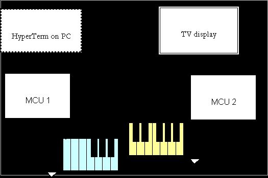
The music keyboard signals are connected as inputs to both MCUs whose ports are configured as input with pull-up enabled. When a button on the music keyboard is pushed, the corresponding port pins on both MCUs are pulled low (to ground). The corresponding music note is digitally synthesized and output by MCU1 to a DAC which outputs an analog signal to the TVs audio input. At the same time, the corresponding note is also drawn on the stave and the video signal is output by MCU2 to the TV.
MCU1 also takes in inputs from HyperTerm on the PC to control the instrument sound that is played. The USART Transmitter is used for the communication link between PC and MCU1.
Hardware/Software Tradeoffs
The music keyboard is made up of individual pushbuttons. To make a full two-octave keyboard, 24 pushbuttons are needed. Connecting the 24 pushbutton signal lines to the MCU would use up 3 of the 4 i/o ports on each MCU, leaving only 1 port available for output to the TV. Since MCU1 (for music synthesis) requires all 8 bits of the output port to produce an 8-bit digital output to the DAC, there would be no more i/o port pins available for other additional functions such as selecting between instrument sounds. Therefore, the hardware constraint of having a limited number of port pins resulted in the sacrifice of two black keys on the bottom end of the two octaves. Our resulting keyboard is as illustrated below:
The two freed port pins are then used for USART communication between MCU1 and the PC, and for additional TV control inputs from pushbuttons called XX and YY to MCU2. The USART communication link between the PC and MCU1 allows for input commands via HyperTerm on the PC to the MCU to select between instrument sounds. Button XX and YY control the display options (sharps or flats) on the stave, the three speed levels for the games and the modes for displaying the notes played or for playing the educational games. The sacrifice of the two black keys is justified by the numerous additional options that the two freed port pins can provide.
Another tradeoff in our project is that to implement both the music synthesis and the TV display concurrently, we have to make use of two MCUs, which also means having to solder our own prototype board since we cannot use more than one STK500. The main reason for making use of two MCUs is that the TV generation routine is timing-critical and the interrupt service routines for the video content-lines have to be entered from sleep mode. With the 2 game functions being implemented during the non-content lines (once per frame), there is insufficient time (and port pins!) left for doing the digital music synthesis to produce chords and different timbre options on the same MCU. Therefore, it is inevitable that we have to use two MCUs. However, one advantage is that programming the music and TV display on different MCUs allows the video and audio features of the project to be tested separately before being integrated together.
Background Physics, Math and Music Synthesis
Musical Instruments and Harmonics
Musical instruments are usually made up of vibrating air columns, vibrating strings or conical air columns. The lowest resonant frequency of a vibrating object is called its fundamental frequency. Most instruments vibrate at all harmonics of the fundamental (A harmonic is defined as an integer multiple of the fundamental frequency).
The nth harmonic = n * the fundamental frequency.
Pitch
The pitch of a musical note depends on its frequency. An octave is a music interval defined by the ratio 2:1 regardless of the starting frequency. The range of standard frequencies (in Hz) used on our keyboard are highlighted as shown in the following table:
|
|
Octave=1 |
Octave=2 |
Octave=3 |
|
|
0 |
A |
110 |
220 |
440 |
|
1 |
A#/Bb |
116.541 |
233.082 |
466.164 |
|
2 |
B |
123.471 |
246.942 |
493.883 |
|
3 |
C |
130.813 |
261.626 |
523.251 |
|
4 |
C#/Db |
138.591 |
277.183 |
554.365 |
|
5 |
D |
146.832 |
293.665 |
587.33 |
|
6 |
D#/Eb |
155.563 |
311.127 |
622.254 |
|
7 |
E |
164.814 |
329.628 |
659.255 |
|
8 |
F |
174.614 |
349.228 |
698.456 |
|
9 |
F#/Gb |
184.997 |
369.994 |
739.989 |
|
10 |
G |
195.998 |
391.995 |
783.991 |
|
11 |
G#/Ab |
207.652 |
415.305 |
830.609 |
Wavetable Synthesis
Wavetable synthesis is quickly replacing FM synthesis in better quality sound cards today. Wavetable synthesis creates realistic, high-quality sound by using actual recordings of real musical instruments. The synthesis technique is similar to the digital sine wave generation that we did in ECE 476 lab 2, but instead of using a table of sine values, a wave lookup-table containing digitized samples for a single period of a particular waveshape is used. In addition, as the musical note evolves, the waveshape is changed dynamically, thus generating a quasi-periodic function in time.
For our project, in order to produce sounds that resemble real musical instruments, we do a modified version of Wavetable Synthesis. Instead of taking a sample of real music sound and storing it in a wavetable, we create our own instrument database by studying characteristic waveforms of various instruments and experimenting with the theoretical harmonic equations in Matlab. We also modulate the wave envelope for different instruments sound effects.
The phase increments needed for the frequency synthesis are calculated in the same way as in lab 2:
phase increment = frequency * (2^24)*40/16MHz
Standards
RS232
RS232 is a physical interface standard specified by the Electronics Industry Association (EIA) for serial transmission of data between two devices using cables, normally carrying between 5V and 12V on both data and control signal lines. The standard allows for a single device to be connected (point-to-point) at baud values up to 9600 bps, at distances up to 15 meters. More recent implementations of the standard may allow higher baud values and greater distances. The RS232 standard defines the pin and plug in terms of size, shape and number of pins. The prefix “RS” means recommended standard. Presently, the standards are now generally indicated as “EIA” standards to identify the standards organization. Our project uses the RS232 standard for the USART communication link between the PC and MCU1. NTSC video
NTSC stands for National Television System Committee, which devised the NTSC television broadcast system in 1953. The NTSC standard has a fixed vertical resolution of 525 horizontal lines stacked on top of each other, with varying amounts of “lines” making up the horizontal resolution, depending on the electronics and formats involved. There are 59.94 fields displayed per second. A field is a set of even lines, or odd lines. The odd and even fields are displayed sequentially, thus interlacing the full frame. One full frame, therefore, is made of two interlaced fields, and is displayed about every 1/30 of a second. The USA is an NTSC country. The NTSC standard is an applicable standard for our video display.
Existing Patents
With regard to intellectual property, YAMAHA owns many electronic music and related patents dating back a quarter of a century. Among its international patents, Yamaha owns US Patent Nos. 4,539,883, 4,584,921, 4,967,635 and 4,974,485, all dating back to the 1970s and early 1980s, covering what Yamaha describes as “core wavetable technologies believed to be in widespread use today.”
PROGRAM/HARDWARE DESIGN
Program Details
Music Synthesis
The code for direct digital synthesis was especially tricky to write. Although the range of audible music frequencies are low enough such that we can make use of interrupts that execute at a regular interval, we faced a lot of difficulty getting the output, be it a sine wave, sawtooth or simple square wave to sound clean. There was always an additional tingly noise which we could not get rid of. However, by writing the code in assembly language in main(), we could produce a clean and smooth wholesome tone for the same kind of output waves. We thus decided to use the assembly language approach for the music synthesis. The output computation in assembly language is looped continuously for 2000 cycles (2000 samples/256 samples per period ≈8 periods) before it exits so that the music keyboard buttons can be sampled again and the corresponding phase increments recomputed.
Waveforms for Musical Instruments
To build up our own musical instruments database, we looked up music literature online and obtained pictures of characteristic waveforms of various instruments. For the clarinet, flute, and trombone, we were able to find actual ratios of their various harmonics. By experimenting with the actual ratios and by trial and error using Matlab for other instruments, we came up with harmonic equations that produce waveforms resembling the characteristic waveforms of various musical instruments. We then proceeded to test the synthesized sounds in our program. After much fine-tuning in the lab, we were able to build up a decent collection of waveform equations that give fairly characteristic musical instruments sounds.
Scheme for Playing Chords
We make use of a direct summation of the digital output of each simultaneously-played note before outputting to the 8-bit DAC. The following diagram illustrates this summation scheme:
Modulating the Envelope for Various Instruments
Different musical instruments have distinct attack and evolution. Brass instruments have a large maximum amplitude attack that builds up over time. It can then fade off (giving the sonorous effect) or be held at constant volume for a period of time. Percussion and plucked string instruments sounds are relatively short-lived since they decay quickly exponentially after the initial impact. Since our music synthesis code is written in assembly language, we use the scheme of dividing by two (right shift by 1) multiple times to approximate the exponential decay.
Displaying Music Stave and Notes on TV
Compared to the challenging code for music synthesis, the code for the TV display was relatively easy to write. Using the existing infrastructure provided by Professor Land for the TV code in lab 4, it was easy to create functions that draw the music staff, music notes, flats and sharps, treble and base clefs on the screen. All we had to do was to figure out the coordinates of the various items.
Implementing the TV Games
The program for the TV games is based on generating a random number between 1 and 30, each of which is assigned a unique note with a sharp, flat or no accidentals. The random number is generated by running timer 0 at a fast speed and setting it to clear on compare-match with number 29. At a fixed time interval for each speed level, the note(s) assigned to the particular random number generated during that time is displayed on the stave. The program then detects the pushbuttons to see if the user plays the correct keys during the time from this moment until the next random note(s) is displayed, while making sure that multiple presses of the same correct note(s) do not score multiple times. In particular, for the game Music Test 2, the program is written such that playing only one note of the chord does not earn the player any point. Both notes of the chord have to be played together in order to score.
Since the timing intervals are set up such that one frame = 1/60 of a second, it is easy to implement the timing of the random notes display as well as the countdown timer for the game (at each speed level) to be over after one full minute.
Hardware Details
The pushbuttons used for the music keyboard are simple mechanical devices that connect an individual wire representing each button to a main wire when the button is pushed. Connecting the main wire to ground would allow the button wires to be pulled to ground when the buttons are pushed. Therefore, the MCUs would be able to detect individual button pushes when the corresponding input port pins with internal pull-ups are externally pulled low.
Because we needed to use 2 MCUs, we had to solder our own STK500 boards. Soldering the 40-pin socket and all the i/o port pin connectors onto the solder board and testing that all the leads were well-connected proved to be the most challenging hardware task. All other pins for VCC, ground, AREF, crystal clock and manual reset were wired as described in class. A schematic of the solder board is shown in the Appendix B. The greatest problem that we faced came from the programming port. It took us many painful hours of debugging to finally discover that certain pins on PORT B had been too loosely soldered.
Detailed schematics of the audio and video setups of our project can be found in Appendix B.
We reused the TV code in lab 4 that Professor Land provided.
Things We Tried but Which Did Not Work
We thought of adding an additional memory feature that would allow the sequence of notes played by the user to be recorded and played back upon demand. However, due to limited port pin constraints, we could only implement it via the USART interface and control it using HyperTerm on the PC. We tried to store the identities of notes played in an array, but a huge two-dimensional array would be needed to be able to store chords. Even when experimenting with a one-dimensional array to store single notes, the playback did not sound like what it should have been. Worse still, normal execution of the music synthesis was also affected and the synthesized sound had an unusual tingly noise, similar to what we got when we used interrupts to execute the music synthesis. We thus abandoned the idea of implementing the memory feature.
For more detail: Music Synthesizer with Interactive TV Display