A project for someone who lights up my life…
As a Christmas present (albeit an extremely late one now) for a long-distance friend, I wanted to build lamps that could “talk” to one another, as in “reflect each other’s color animations when simulated.” This involved a lot of frustrated screaming into pillows, late night confusion on why the circuit suddenly stopped working, and hours of debugging over hot cups of tea (not to mention weeks and weeks of research and taking notes to include for this long tutorial). But at long last, I have lamps that communicate through Adafruit IO:
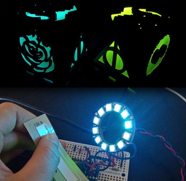
- In lamp #1, a softpot connected to neopixels controls the pixels’ animations
- When the softpot is pressed in a specific location, the pixels perform the corresponding animation
- The arduino connected to the softpot sends this sensor reading to a raspberry pi
- The raspberry pi is connected to the internet though a wifi dongle, so it can send the sensor reading to a feed in Adafruit IO
- The raspberry pi of lamp #2 registers the new value in the feed and sends it to its arduino
- This arduino animates its neopixels based on the value and all is good 🙂
Now, before anyone becomes nervous from the electronics and microcontrollers, allow me to assure you that I began as an absolute amateur. The farthest I had ever gone with Arduinos were the level 2 built-in sketches, I had never touched a raspberry pi before, and MATLAB was the only programming language I knew, besides how to print “Hello World” in python. Luckily, I had a EE friend to point me toward the right resources and help with troubleshooting (bless his soul). So if you’re daunted by a steep learning curve, fear not.
Also, if you’re worried about cost barriers, I did my best to minimize out of pocket costs of the components (~$80 for me). Admittedly, there are a few parts that would be best to borrow if possible, like keyboards and monitors, but try asking around or going to a local makerspace.
Step 1: Table of Contents

TLDR: Go to step 6 to begin building a lamp, or just keep reading along to get background info as well.
I have a LOT of excess information in this tutorial besides the bare bones of how to make the lamps. This is partially my personal documentation of the learning process for future reference (I included my rough pseudocode, general thought process, research notes + reference links for different functions, etc.), but also a guide of things I tried out to help you if you want to make alterations to the design. For example, if you want to get rid of the Arduino component and control the softpot and neopixels through the raspberry pi, see the next step for how I got it to partially work without using logic level shifting. Oh also — if you have any input on how to solve any approaches/problems that I encountered and abandoned along the way, please leave a comment!
The first few steps are general background info and things I tried: Choosing raspberry pi and arduino, intro to neopixels + softpot, adafruit IO, serial connection between arduino and raspberry pi.
After that is the entire workflow of how to build the lamps: files for the codes, setting up the micro controllers, building the neopixel + softpot circuit, etc.
The last step covers my final reflections and possible ideas to build on this lamp design.
Quick disclaimer: I rushed this project towards the end so there are still some buggy parts in the code/logic! The lamp functions but you need to send values to the feed twice: the timing is such that a value gets wiped before it can be sent, and I’m still trying to circumvent that. But the recipient is having heart surgery soon so I needed to get the lamp sent first and optimized later!
Step 2: Arduino Plus Raspberry Pi
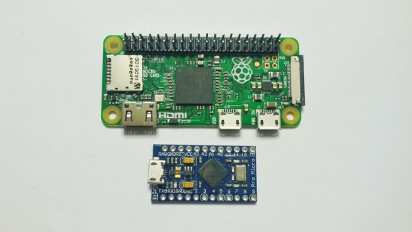
Why do I have two micro controllers for this project? Well, the network connection to Adafruit feeds and dashboards requires internet access, and for arduinos that usually involves expensive wifi shields. Instead, I used a raspberry pi zero with a wifi dongle (~$15 compared to $30).
But why do you need an arduino then — why not just control the neopixels and softpot off a raspberry pi? I originally pursued this idea, but had little luck getting reliable data from the softpot. Two main problems:
- Neopixels use 5V logic while the raspberry pi zero outputs 3.3V standard
- Raspberry pi zero is not capable of analog-to-digital conversion (ADC) by itself (so can’t work directly with softpot)
- Documentation here
I did my best to circumvent these issues (fueled by my desire to save money, as always). Even though adafruit doesn’t recommend powering neopixels off the 5V GPIO pin of the raspberry pi, I managed to get away with it by connecting the 5V pin (GPIO pin 2) to the neopixel power, ground pin (GPIO pin 6) to the neopixel ground, and pwm pin (try GPIO pin 12 or 18) to neopixel data in. Then use Jeremy Garff’s rpi_ws281x library to control the animations using python. See this guide or this one for how to install and use that library. If you’re still worried about the logic level, you can use logic level shifters as described by Adafruit.
Now that the neopixels worked on the pi zero, I wanted to control them based on sensor readings of a softpot. There was surprisingly little documentation of how to use a softpot with raspberry pi, so I cobbled together information from tutorials with force sensitive resistors (FSR). Again, there’s the problem with analog-to-digital conversion, as described here. You could get ADC chips to make the readings compatible with the raspberry pi, but frugal as always I looked into ways to use an RC circuit. The idea is that you have your FSR (soft pot in my case) and capacitor in series. Set the voltage to a square wave via pwm to charge up the capacitor. How fast it fills up depends on the value of the resistor. This documentation was helpful for setting something up, but no matter what I tried I got rubbish values. I thought it might be something with calibration, and it probably could’ve been done with an oscilloscope to reliably monitor everything, but I threw in the towel and got an arduino to handle both the softpot and neopixels — no 5V conversion or ADC to worry about, not to mention plenty of documentation online.
Useful references:
- raspberry pi zero pin out (the GPIO pins and what they can do)
- arduino pro micro pin out
- reference for arduino coding
- reference for python coding (warning: it’s a bit overwhelming)
Step 3: Getting Familiar With Neopixels and Softpots
All right, so what are neopixels? They’re addressable LEDs that can be controlled by the micro controller of your choice. Here’s Adafruit’s Uber guide to handling them, if you’d like in-depth info. They expect 5V logic so raspberry pi are generally not preferred for controlling them (see previous step for my angst-y explanation). There are three main pins on the neopixels: power (connect to 5V), ground (connect to ground; it’s the pin with the triangle), and data in (connect to a free pin to relay messages between the pixels and microcontroller for animation). An alternative would be DotStar LEDs, but neopixels were better documented for an amateur like me to begin using.
Now soft potentiometers, aka softpots, are resistive sensor strips that change their resistance based on where you touch them. They also have three pins: power (connect to 5V), ground (connect to ground), and wiper (outputs an analog signal — connect to any analog input pin). Sparkfun has great documentation on how to hook them up in circuits and handle them, but the main thing to note is that there should be a resistor between the wiper middle pin and ground to hold the value at 0 whenever the soft pot isn’t touched (i.e. so it doesn’t “float,” as the cool kids say). The leads are pretty fragile since repeated bending creates fatigue that causes them to snap easily, so I used plenty of heat strink for stabilization (and prevent the leads from touching each other, creating a short circuit.
For my lamp, I hooked up softpots to control the neopixels so that you would end up with different animations in the neopixels based on where you touched the softpot (i.e. based on the changing resistance of the softpot, which the arduino would read, analyze, and send instructions to the neopixel).
Summary references (for coding with arduino):
Step 4: Adafruit IO
There are many different platforms for IoT (ThinkSpeak, Blink, AWS) but the one I used is Adafruit IO.
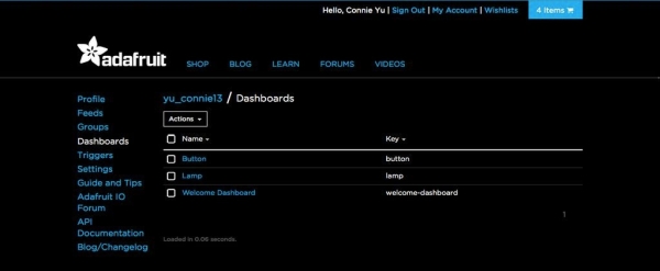
Adafruit offers a platform for people to tinker around with Internet of Things (IoT) projects on io.adafruit.com. It’s still in beta mode and admittedly a bit buggy, but it works well enough for my simple purposes. Essentially you have dashboards with blocks that can be stimulated (toggle buttons, sliders, gauges, etc.) and the data would be sent to feeds where you can monitor the blocks’ actions. Data policies are here: the max rate is 2 samples per second, each feed can have 50,000 data points, and data retained for 30 days. This project is pretty simple (and timing not too crucial) so I didn’t worry too much about encountering problems with data storage/collection.
Adafruit’s tutorials (digital input and digital output) use npm for the package manager and node.js stream application program interface (API) and to familiarize myself with it I did my best to follow the tutorials for raspberry pi connection. However, I had a lot of trouble downloading the library dependencies using npm, so my friend suggested that I use python’s pip instead. This is a great resource for using pip with adafruit IO, and this resource is an exhaustive list of using pySerial (for communicating between the raspberry pi and arduino via the serial port.)
This platform gives you an AIO key to put in the client field when you want to send and retrieve data, so while you don’t need to know python pip, you will need to alter my python code to match your specific cases. Just a heads up!
References:
- Adafruit feeds
- Adafruit dashboards
- Python pip to interact with Adafruit IO
- pySerial API
Step 5: Serial Communication Between Arduino and Raspberry Pi
Communication between the raspberry pi and arduino is possible via the serial port; for more in depth exploration of the serial monitor, see this. Essentially, when the arduino registers a value from its softpot, that value is sent to the Adafruit IO feed through serial port to its raspberry pi (which is the one that has internet access and thus access to the feed). The other lamp’s raspberry pi notices a new incoming value and sends that to its own arduino via serial port to control its neopixels, thus synchronizing both lamp’s animations.
Sounds simple in concept, but implantation is always a HUGE struggle; behind the concept were weeks of annoying debugging. Key problems:
- I wanted to avoid using a USB connection so I wouldn’t need to leave a USB hub to provide more ports to the raspberry pi (since it has two USB ports, one that would be needed for power and the other one for wifi). Thus I wanted to do serial connection through the TX and RX pins (transmission and receiving pins, respectively).
- You would think that it’s as simple as connected the TX of one to the RX of the other, and vice versa, but of course that doesn’t work out. This is tricky because the arduino outputs 5V logic while the raspberry operates on 3.3V logic: thus, while the arduino’s RX pin can just be connected to the raspberry pi’s TX pin (since arduino 5V can read lower logic), the arduino’s TX pin must go through logic level shifting from 5V down to 3.3V in order to be connected to the raspberry pi’s RX pin. See this website for a simple guide, and this website for other suggested methods of doing so.
- All right, logic level shifting. To save a little $ (and time for shipping), I build a simple voltage divider circuit using a few resistors (keep the resistors’ power rating in mind so you don’t melt the poor things!) before connecting the arduino TX pin to V_in of the divider and the raspberry pi RX pin to V_out.
- Then make sure to follow the steps outlined here on preventing Linux (RPi’s operating system) from using the serial port and interfering with your connection.
- But of course that didn’t work! D:
- I played around a bit to try making it work. One thing is that to generate output on the arduino pro micro, you need to use the Serial1 class — i.e. change the Serial.____ commands to Serial1._____ .
- And… it still didn’t work. I was stumped and frustrated so after two days of researching and testing, I just bought another $5 USB hub and used a USB A to micro B cable to connect the RPi to the arduino. And of course that worked the first time around.
- Now that the serial ports are connected, everything’s fine, right?
- LEFT. (heh; word play…)
- The tricky part this time is sending numbers through serial connection, since there are many classes. You could send what you think is a number, but once the other microcontroller reads it you might realize that it was sent as a string in ASCII code. But then your arduino code reacts to the ASCII code inputs separately and thus Houston, we have a problem…
- It took a bit of trial and error to get the correct output to the serial port, but referencing this site I found Serial.parseInt() that did the trick for the arduino reading the raspberry pi’s output as an integer.
- And then it just came down to writing some code to make everything work…
- for coding in Python to have raspberry pi communicate to arduino: pySerial
- example code for using python ser.write() function
- for coding in Arduino’s C to have arduino communicate to raspberry pi: Serial
- example code of arduino receiving data and sending data
- for coding in Python to have raspberry pi communicate to arduino: pySerial
- Well, writing code is hard. Logic is difficult to get right. And data types smh.
- I had a lot of trouble with getting the order of commands down D: so note for future me: be sure to write lots of pseudocode so you can plan your order/logic in advance!
- A major problem I had was with Arduino’s auto reset: I didn’t know that starting the serial monitor for the Arduino also restarts the sketch. Documented here, here, here, and here: The first two links are forum topics of people having trouble, and the last two links are good resources explaining the phenomenon and suggesting alternatives.
- I wanted my code have feedback: if it’s in the middle of an animation, it should still check the serial port for communication from the raspberry pi to see if it should break out. However, by checking the serial port, it automatically broke out of the for loop since the sketch would restart. You can’t imagine how much time I wasted trying to figure out what was going on (I had some inequalities that would break out of the for loop even though they shouldn’t have — 20 > 101??).
- Two options:
- Edit my python code so the raspberry pi would not send over values until you needed to break out, and then you’d just have to send the animation trigger value twice
- Edit my Arduino code and use the Serial.peek() function (read the API, my friends)
- peek() won’t cause an auto reset but it’ll return a byte of the serial message. Then figure out a way to correspond that byte to break out or now.
Good references:
Step 6: Workflow Overview
A more fleshed-out explanation the workflow for building the lamps:
- Prepare equipment
- Make sure you have everything — cables for hooking up to monitors, etc. as described in the materials step
- Set up micro controllers
- Arduino (no need to hook up to monitor — just plug it into your computer)
- Download the Arduino software on your computer
- Dowload the .ino file for it (attached to this step)
- Hook up the circuit with neopixels and soft pots, test on breadboard before soldering to stripboard
- Raspberry pi (hook up to monitor, keyboard, mouse)
- Ready your micro SD cards for use with a raspberry pi (flashing, installing OS)
- Update existing systems (sudo apt-get update)
- Set up Wifi for you and recipient
- Set up Adafruit IO
- Make an adafruit account and sign up to be a beta user
- Create a feed that will receive and record data
- Create a dashboard where you can adjust a slider to reflect softpot readings
- Downloading python IDLE and .py code
- Set up python code to run on set up (so no need for keyboard/monitor/peripherals on the pi zero)
- Arduino (no need to hook up to monitor — just plug it into your computer)
- Build other lamp
- Build lamp covers
Step 7: Materials
Necessary components: (with approximate cost and applicable links) — you might have some of these on hand, such as the SD cards (flash them yourself to save $$)
- 2x arduino pro micro ($4 each)
- 2x raspberry pi zero ($9 each with all adapters)
- 2x mini-HDMI converter
- 2x micro-B OTG USB
- 2x 40 pins for GPIO
- 2x micro SD cards ($4 each; at least 4GB or higher)
- 2x neopixel rings ($7 each; I used 12 pixel rings to keep current requirements down, so I could power everything off one power supply)
- 2x soft potentiometers/softpot ($5.50 each)
- 2x 5V/2A power supplies ($6 each)
- 2x wifi dongles ($10 each)
- resistors (1kOhm or above should be fine)
- heat shrink (to protect the softpot leads — they’re fairly fragile after repeated bending)
- breadboard for protyping, stripboard for soldering permanence
- electrical wire (solid core copper insulated in plastic sheathing like this)
Necessary equipment for operation: (besides the obvious ones like computer and internet access) (try to borrow from friends or go to a makerspace if possible)
- computer monitor (with HDMI port)
- keyboard
- HDMI cable
- mouse (NO gaming mouse or anything special, unless you have a powered USB port to the raspberry pi! Make sure it’s compatible with your USB hub and with Linux — for example, my wireless Logitech mouse didn’t work since it requires Mac OS or Windows but not Linux)
- USB hub ($6)
- USB A to micro B cable (you probably have one from an android phone charger)
- multimeter
- soldering iron + solder
- heat gun (optional but recommended for desoldering the TX and RX pins)
Materials for lamp: (feel free to come up with any other design of course, but I just went with a customized cube)
- quarter inch plywood
- laser cutter access or amazing scroll saw skills
- wood stain
- eighth inch acrylic
- glue
- vector graphics program
At least for me, out-of-pocket cost came to about $80 to make two lamps, but admittedly I had the computer monitor, soldering irons, and other equipment such as laser cutter and scrap wood. If you plan this as a Christmas gift, know that pimoroni.com offers significant discounts for many electronic components during Black Friday so if you buy your components then, you could still finish by Christmas… *wink nudge*
Source: Network-Connected Lamps (IoT for Beginners)