
Summary of An NRF24L01+ and FTDI Ready Atmega 328P-PU (3.3V, 500 MA) Microcontroller With Dual Power Capability, Undervoltage, Hysteresis, and Thyristor-Crowbar Overvoltage Protection
This article describes a 3.3V microcontroller board featuring an Atmega 328P-PU, nRF24L01+ wireless support, and dual power inputs (AC/DC adapter and battery). It includes robust safeguards like under-voltage lockout with hysteresis, overvoltage protection via a thyristor crowbar, and a resettable PTC fuse. The design optimizes for low quiescent current to extend battery life, achieving approximately 1.6 years of operation on a standard LiPo cell with sleep cycles.
Parts used in the Microcontroller Board:
- Atmega 328P-PU microcontroller
- 16 MHz crystal oscillator
- nRF24L01+ wireless transceiver
- STM809 MPU Reset IC
- MCP1825 Low Dropout (LDO) linear regulator
- Thyristor-based Crowbar circuit
- Resettable 500 mA PTC fuse
- 6-Pin female header for FTDI adapter
- 8-Pin female connector for wireless transceiver
- Barrel connectors for dual power input
This board is designed to safely drive a 3.3V microcontroller and connected accoutrements. It supports primary and backup power sources and provides numerous over and under voltage safeguards.
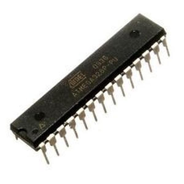
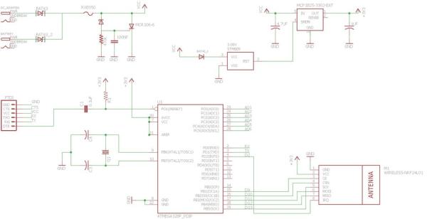
The microcontroller here is a bare-bone, no-frills Atmega 328P-PU with no leds, driven by a 16 MHz crystal. An 8-Pin female connector is wired up to the Atmega chip and the 3.3V power regulator for a wireless transceiver to be connected. The transceiver board here can be any of the nRF24L01+ family and there is more than enough power to drive even the PA+LNA 1100 meter version at its highest power setting.
The Atmega programming connections (RX,TX, RST) are also wired up to a 6-Pin female header which is FTDI adapter ready. Just plug in the adapter and connect to your laptop or desktop with a USB-mini USB cable and it is ready to be flashed.
The circuits’ dual power connections are assumed to be an AC/DC adapter and a battery backup. It can, of course, also be single-power source driven on either of the two barrel connectors.
As the circuit is designed to be powered by battery, at least as a backup, lower quiescent current is desired to support longer battery life.
The quiescent draw of this circuit with an Atmega 328-PU and an nRF24L01+ board was measured at ~150 uA @ 5V input and only 5uA when there is not enough power to turn on the 3.3V regulator. (A 3.7V LiPo, 4.15-4.20V when fully charged is the battery used here).
The battery life calculation numbers for a 56 second sleep-cycle configuration:
(Using 60% guideline and 5000mAh capacity rechargeable battery)
- 150uA * 56 = 8,400 uA (56 second sleep cycle)
- 2000uA * 2 = 4000 uA (2 second active cycle)
- 12,400 uA divided by 58 seconds = 214 uA (power usage per second)
- 3000 mAh (60% of 5000) / 214 uA = 14,018 hours on LiPo Battery
- 14,018 / 24 hrs. = 584 days = ~1.60 years battery life
Lengthening the sleep cycle or shortening the duty cycle draw means longer battery life.
When powered and the voltage provided falls below the minimum voltage, here ~3.65V, the battery is disconnected from the regulator. This will save a partially discharged battery from being completely drained and destroyed.
The circuit will reconnect the battery again when the voltage at the MPU reset IC exceeds ~3.75V, providing hysteresis by having an upper and lower threshold to eliminate multiple transitions when the power is at or near disconnect level.
Against overvoltage, this circuit uses a simple Thyristor-based Crowbar to protect the 3.3V regulator and provide current flow control using a resettable 500 mA PTC fuse.
Should the wrong adapter or a power supply greater than 6.5V be connected to either of the barrel connectors, the crowbar circuit shorts the power rails, and causes the PTC fuse to inhibit the current flow. Due to the associated voltage drop, the MPU reset IC will also disconnect power from the regulator.
Once the overvoltage is removed, the PTC will cool and reset. The board will again turn on once a power source above the minimum ~3.75V and below the maximum ~6.5V is connected.
An STM809 MPU Reset IC is used to monitor the input voltage (post crowbar) and to cut off power to the regulator when the input voltage falls below the minimum input voltage (~3.65V).
The MCP1825 regulator used here is a 500 mA Low Dropout (LDO) linear regulator that provides high current and low output voltage. The 5 Pin versions have a Shutdown (SHDN) pin.
The SHDN pin requires a digital HIGH to be present for the regulator to produce its 3.3V output. A digital LOW will cause it to shut down. This is accomplished by connecting the SHDN pin of the MCP1825 to the RST output of the STM809 IC.
This microcontroller circuit has very little voltage drop, enough hysteresis to stop battery recovery cycling, overvoltage protection, and is ready to have any sensors or actuators added as required.
Read More: An NRF24L01+ and FTDI Ready Atmega 328P-PU (3.3V, 500 MA) Microcontroller With Dual Power Capability, Undervoltage, Hysteresis, and Thyristor-Crowbar Overvoltage Protection
-
What is the maximum power supply voltage allowed?
The board should not be connected to a power supply greater than 6.5V. -
How does the circuit protect against overvoltage?
It uses a Thyristor-based Crowbar to short power rails and trigger a resettable PTC fuse to inhibit current flow. -
What happens when the input voltage drops below 3.65V?
The STM809 IC cuts off power to the regulator to prevent draining the battery completely. -
How is the battery recovery cycling prevented?
Hysteresis is provided by having an upper threshold of ~3.75V and a lower threshold of ~3.65V. -
Can this board drive the PA+LNA version of the transceiver?
Yes, there is enough power to drive even the PA+LNA 1100 meter version at its highest power setting. -
What is the estimated battery life with a 5000mAh battery?
Approximately 1.60 years or 584 days using a 60% capacity guideline and a specific sleep-cycle configuration. -
How do you program the microcontroller?
Plug an FTDI adapter into the 6-Pin female header and connect to a computer via a USB-mini USB cable. -
What type of battery is recommended for this circuit?
A 3.7V LiPo battery is used here, which charges between 4.15V and 4.20V.
