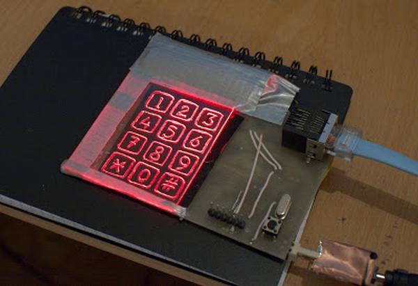
Summary of AVR-based Sensor Keyboard
A modern microcontroller can implement a touch sensor matrix using QMatrix technology by transferring charge from PCB sensor pads into a tank capacitor, then measuring discharge time with a controlled current. Touches reduce transferred charge, changing the measured time and allowing detection. The author built a from-scratch implementation using a tank capacitor, switches for pumping and measurement, and an analog comparator with a large Rslope to make timing measurable.
Parts used in the QMatrix-based Sensor Matrix:
- Microcontroller (modern MCU with GPIO and analog comparator)
- PCB sensor pads (Ckey)
- Tank capacitor (Ctank, 4.7nF used)
- Switches for drive and measurement (Sdrive, Sslope, Stop, Sbottom, Sc — implemented via MCU or external switches)
- Rslope (large resistor to limit discharge current)
- Analog comparator
- Interconnects/traces for sensor matrix
A modern microcontroller has almost everything that’s needed to implement a touch sensor matrix. There are several sensing technologies: IC manufacturers typically advise using certain tech, sometimes they offer ready to use hardware- or software-based solutions. I was curious to try to implement a sensor matrix entirely from scratch all by myself. Here’s how it worked out.
Theory of Operation
I chose QMatrix technology as a basis for my experiment, mostly because I’ve heard about it before and because I liked their whitepaper, which I really recommend to read, here: QMatrix™ Technology White Paper. The point is to transfer the charge through the sensor capacitance to a tank capacitor gradually, until a charge sufficiently large to be measured builds up. After that, a current is applied to the tank capacitor and the time that it takes to reach zero crossing is measured. When sensor surface is being touched, the fingers steal part of the charge to be dissipated by the body and less of it gets transferred to the tank capacitor. This difference can be measured and tried to tell if a button is being touched or not.
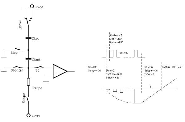
he QMatrix Technology Whitepaper already has a perfect illustration of what’s going on, but I drew my own version to aid the explanation. On my drawing: Sdrive is a switch that allows to pump the charge through the sensors; Sslope is what allows the current to the tank capacitor during the measurement phase. Stop and Sbottom are the switches that flip the capactor. Sc connects the analog comparator. Ckey is the sensor, a pattern on the PCB. Ctank is an additional capacitor, 4.7nF in my case. Rslope is fairly large, it is to limit discharge current and make the time measurable.
The process of charge transfer to the Ctank is very similar to the work of a charge pump converter (see Horowitz, Hill: The Art Of Electronics, §6.23).
Read More: AVR-based Sensor Keyboard
- What sensing technology did the author choose?
The author chose QMatrix technology as the basis for the experiment. - How is charge transferred to the tank capacitor?
Charge is pumped through the sensor capacitance into the tank capacitor via a switching network similar to a charge pump. - What indicates a touch on the sensor?
A touch steals part of the charge so less reaches the tank capacitor, changing the measured discharge time. - What component is used as the tank capacitor and what value was used?
Ctank is used as the tank capacitor and a 4.7nF capacitor was used in the experiment. - Why is Rslope made fairly large?
Rslope is large to limit the discharge current and make the time to zero crossing measurable. - What role does the analog comparator play?
Sc connects the analog comparator to detect the zero crossing during the tank capacitor discharge measurement. - Which switches are involved in the charge transfer and measurement phases?
Sdrive pumps charge through the sensors; Sslope allows current to the tank during measurement; Stop and Sbottom flip the capacitor; Sc connects the comparator. - What inspired the switching approach used in the design?
The charge transfer process is similar to a charge pump converter as described in The Art Of Electronics.