Summary of Arduino LFO Waveform Generator V2
This project describes a second-generation Arduino-based Low Frequency Oscillator (LFO) generator using an Atmega 168/328 processor and a MAX522 DAC. It produces arbitrary waveforms for guitar amplifier tremolo/vibrato circuits, featuring a hand-wired perf-board design with floating ground isolation and specific bias adjustment for LED/opto-coupler drive.
Parts used in the Arduino LFO Waveform Generator V2:
- Arduino microprocessor (Atmega 168 or Atmega 328)
- MAX522 8-bit serial DAC
- Full-wave Schottky diode bridge rectifier
- 2200uF filter capacitor
- 78L05 voltage regulator
- RC low-pass circuit
- Variable voltage divider (potentiometer)
- TLC2272 CMOS rail-to-rail op-amp
- Front panel LED
- Light Variable Resistor opto coupler
- 1.5K resistors
Introduction
This project uses an Arduino microprocessor and a MAX522 8 bit serial DAC to produce arbitrary low frequency oscillator (LFO) waveforms. These waveforms are useful for driving a tremolo/vibrato circuit in a guitar amplifier such as the Lil Tiger or the Hammonator 2RVT. This is a second generation version of this project, see the first version for reference.

The first prototype of this project was build using the Arduino Diecimila development board and an Arduino prototype shield for the DAC and associated parts. The original assembly can be seen in the photographs of the Lil Tiger project. This final version of the circuit was built using just the Arduino’s Atmega 168 (or Atmega 328) processor chip on a hand-wired perf-board as shown in the above photo. The microprocessor should be programmed on the Arduino board then moved to the stand-alone LFO board.
Hardware
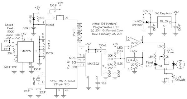
The 7.5VDC power to the board comes from a full-wave Schottky diode bridge rectifier and 2200uF filter capacitor that is connected to the 6.3VAC filament winding of a vacuum tube power supply. The 7.5V is regulated down to 5V using a 78L05 regulator. The 7.5V and 5V sources power the processor, DAC and op-amp. Note that when this circuit is used with the Lil-Tiger amp, the LFO ground is not connected to the chassis ground, it is floating at 3.15VAC. Be sure to keep the LFO circuit board electrically isolated from the chassis.
The DAC is a MAX522 that is connected to Port B on the Arduino, the port is setup to use the SPI (serial) output mode. The DAC output goes to an RC low-pass circuit to remove the waveform stairsteps. The smoothed waveform is sent to a variable voltage divider that is used to set the LED bias voltage to 1.4V. The output of the voltage divider drives two sections of a TLC2272 CMOS rail-to-rail op-amp. Note that the LED bias adjustment changes the waveform amplitude, adjust the bias first then adjust the LVR drive.
One op-amp section drives the front panel LED and the other drives the Light Variable Resistor opto coupler. Note that the TLC2272 op-amp has a fairly low maximum output current, the 1.5K resistors limit the LED currents to below this level. The low drive level is perfect for the opto-coupler, a high efficiency LED should be used for the front panel LED indicator.
The bias is set so that the LED is just turning on when the DAC is set to output zero volts, red LEDs typically turn on at around 1.4V. The bias adjustment can be preset by adjusting the potentiometer to 26.5K. A more accurate bias adjustment can be done by monitoring the output of either TLC2272 op-amp section with an oscilloscope in DC mode and setting the low point of the waveform to 1.4V. Due to the above mentioned floating ground situation, the LFO should be powered by an external 7.5VDC supply when adjusting the LED bias.
Read More: Arduino LFO Waveform Generator V2
- What is the purpose of this Arduino LFO project?
This project uses an Arduino microprocessor and a MAX522 DAC to produce arbitrary low frequency oscillator waveforms useful for driving tremolo or vibrato circuits in guitar amplifiers. - How is the power supplied to the board?
The board receives 7.5VDC from a full-wave Schottky diode bridge rectifier and 2200uF filter capacitor connected to a 6.3VAC filament winding, which is then regulated down to 5V by a 78L05 regulator. - Can I use the Arduino Diecimila board for this final version?
No, the final version was built using just the Atmega 168 or Atmega 328 processor chip on a hand-wired perf-board, though the processor can be programmed on an Arduino board first. - How do you remove waveform stairsteps in this circuit?
The DAC output goes to an RC low-pass circuit designed specifically to remove the waveform stairsteps before smoothing the signal. - What is the correct LED bias voltage setting?
The variable voltage divider sets the LED bias voltage to 1.4V, which is the typical turn-on voltage for red LEDs when the DAC outputs zero volts. - Why are 1.5K resistors used in the circuit?
The 1.5K resistors limit the LED currents to below the maximum output current level of the TLC2272 op-amp sections. - Is the LFO ground connected to the chassis ground?
No, when used with the Lil-Tiger amp, the LFO ground floats at 3.15VAC and must remain electrically isolated from the chassis. - How can I accurately adjust the LED bias?
You can monitor the output of either TLC2272 op-amp section with an oscilloscope in DC mode and set the low point of the waveform to 1.4V. - What type of supply should be used when adjusting the LED bias?
The LFO should be powered by an external 7.5VDC supply when adjusting the LED bias due to the floating ground situation.