Summary of Object Avoidance Microbit Robot Using the Kitronik Motor Controller
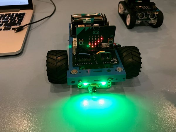
This article details the construction of a BBC Microbit-based object avoidance robot using a Kitronik motor driver board. The project aims to create a low-cost, educational chassis that incorporates IR sensors for obstacle detection and Neopixels for visual feedback. Built with Tamiya motors and plastic strips, the robot utilizes MicroPython and features an expandable design for future sensor additions.
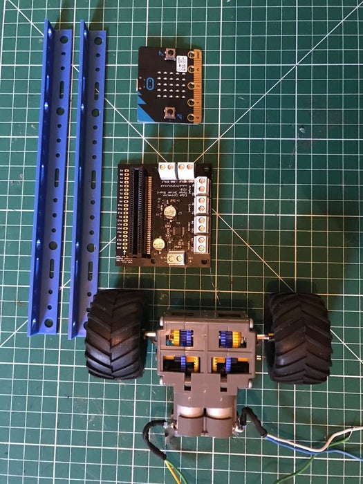
Parts used in the Object Avoidance Microbit Robot:
- BBC Microbit
- Kitronik motor driver board v2
- 2 x Tamiya motors with gearboxes
- 4 x AA battery box with rechargeable batteries
- Plastic strips for chassis frame
- Female to female jump leads
- 1 x caster wheel
- A4 sheet plastic (1.5mm thick)
- 2 x Neopixels
- IR object avoidance sensor
Having already experimented with creating a robot using a cheap motor driver board, I decided to look at the one provided by Kitronik, I liked the look of it as it came with easy to use screw terminals to attach wires and had 4 inputs by default.
The nicest thing is that if you get the v2 board (second version) it also has an expanded section which allows you to solder a 20 pin header onto it and use the full range of extended Microbit ports.
Aims
- Create the robot chassis keeping costs to a minimum or allowing to reuse old parts you may have available.
- Reuse old motors I had (in this case Tamiya motor gearbox combinations)
- Create a good base I could provide in simple kits to students attending one of the workshops I plan to run this year.
- Add IR sensors to create a way for the robot to avoid close objects.
- Add neopixels so it can use different colours and sequences to show what the bot is doing
- Allow more sensors to use the expanded pins on the motor driver board perhaps in future updates
- Use micro python as the language of choice.
Step 1: Equipment Required
- BBC Microbit link
- Microbit Kitronik motor driver board link
- 2 x motors and wheels of your choice, I used Tamiya motors with gearboxes as I had some already. link
- 4 x AA battery box for the motors, rechargable batteries or a power supply of your choice
- Some plastic strips or other to make a chassis out of. I used a couple of these link
- female to female jump leads to connect microbit edge connector to IR sensors and Motor board
- 1 x caster wheel from DIY shop / store
- Some plastic sheet, I used some A4 sheet plastic sheets 1.5mm thick, which you can score with a knife and snap, or can cut with scissors. This is great for panels on your chassis to to build sides later on and enclose all the electronics. link
- 2 x Neopixels link
- IR object avoidance sensor link
Tools
- Cross head and flat screwdriver (small)
- small drill to drill holes in plastic of chassis
- Soldering Iron and solder
- Hot glue gun (optional) or glue
Step 2: Build the Chassis
For the chassis I wanted to start with a basic frame that would give me options later to perhaps build upon, so adding a body to cover the electronic could be a future option.
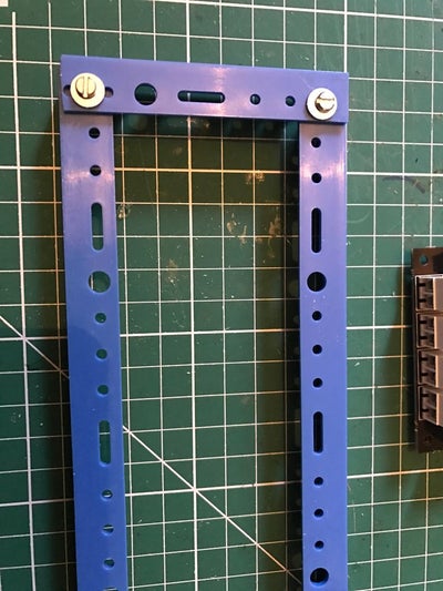
I started with 2 plastic strips and cut them to a length I thought my bot with 2 wheel drive and a caster wheel would need.
I placed the motors in place to work out the width I would need and attached them using the 2 fixing holes available. I cut the chassis to allow the motor shafts to stick through the middle of these two side struts of the chassis.
Next I fitted the front and back struts connecting with a single screw and nut at each corner. I had to drill these holes with my dremel as the holes already there were not exactly where I needed them.
Once the frame of the chassis was complete and motors fitted I added the Kitronik motor driver board. Full documentation is available here https://www.kitronik.co.uk/pdf/5620%20Motor%20Driv…
I decided to put it on my chassis with the expanded pins section at the front, and face the microbit that way as well when slotted in place. Like many microbit expansion boards they allow the microbit to be fitted in either direction. Its important to read the expansion boards notes to see if there are any limitations when doing this such as some pins not available.
I also added the wheels to the motor gearbox output shafts and fitted a rear castor wheel.
Step 3: Adding an IR Distance Sensor
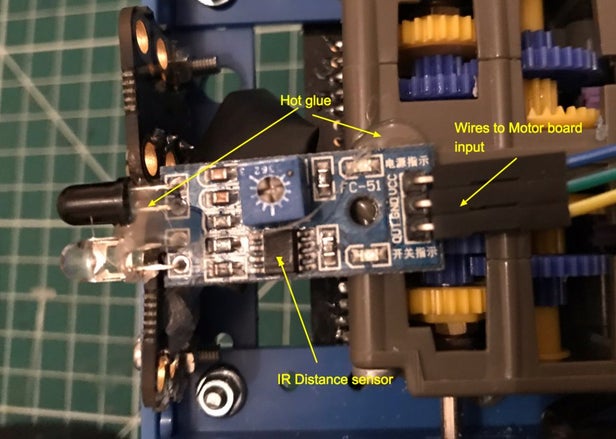
Initially I wanted to get used to using just one of these sensors, I had tried before using Arduinos and the Crumble controllers however I had found them very sensitive, and they come with a sensitivity adjustment available by screwing in or out an onboard potentiometer. My plan this time was to find settings that worked and try and get them to work each time and not need constant readjustment before use. My thoughts here were if I can use the accelerometer as a backup I can then not be too concerned if a sensor doesn’t behave as I should have another way of detecting movement and potentially cutting power to the motors.
Step 4: Complete Wiring
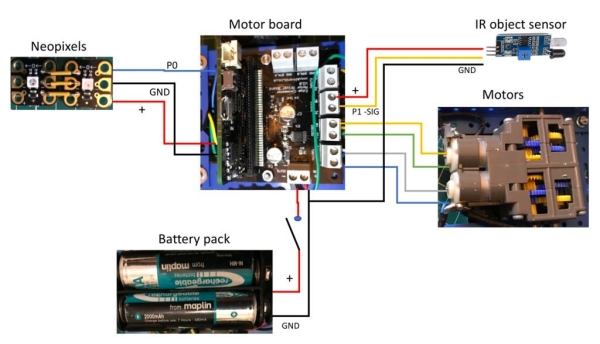
The wiring is reasonably straight forward, refer to the image here as a guide on what I did.
Step 5: Add the Neopixels
I also wanted to add some neopixel lights so the bot could tell me by colour what was happening as well as using the built in microbit’s display.
The neopixels I used were sold as a Crumble microcontroller accessory, I like these as they are not too small to work with and have holes to add male ended pins or wires, or can be used with crocodile ended leads.
I decided to use two side by side so first soldered 3 pieces of wire between them connecting the 3 connections required.
Positive, negative and signal
I then soldered 3 jump lead wires which were female to female so they would connect easily to the extended motor controller connections, where I had earlier soldered the header pins.
These I pushed in so I connected a Positive, negative and signal connection to these extended pins.
The pin you use on the extended header needs to be capable of analog output, so for this I used Pin 0.
I tested this with a simple micro python script (see image), this allowed me to test both neopixels, you could add more and the loop here would cycle through them all.
Step 6: Battery Power Supply, Holder and Power Switch
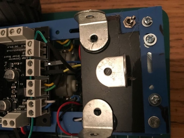
The good news is the Kitronik motor driver board also powers the plugged in Microbit. So using a 4 x rechargeable AA battery pack in a holder and adding a switch is the perfect combination, If you have some Lipo battery pack that would be lighter than this, but its what I already had available.
I hot glued some metal angle brackets used for small shelfs from a DIY store. These would stop the battery pack to slide about when the robot moved, but would be easy to remove to recharge or to access other parts of the chassis.
I added a switch and attached it to the chassis by creating a hole to push it through, and then soldered the wiring required.
Source: Object Avoidance Microbit Robot Using the Kitronik Motor Controller
- What version of the motor driver board is recommended for expanded connectivity?
The v2 board includes an expanded section allowing you to solder a 20 pin header for full range extended Microbit ports. - How can the robot indicate its status visually?
You can add two Neopixels to display different colors and sequences showing what the bot is doing. - Which programming language is used for this project?
MicroPython is selected as the language of choice for controlling the robot. - Can the Neopixels be connected directly to the standard Microbit pins?
No, the signal pin used must be capable of analog output, so Pin 0 on the extended header was used. - How is the power supply managed for both the motors and the Microbit?
The Kitronik motor driver board powers the plugged in Microbit, so a single 4 x AA battery pack supplies both. - What tool is suggested for drilling holes in the plastic chassis?
A small drill or dremel is required to drill holes in the plastic where existing mounting points do not align. - How are the Neopixels wired together before connecting to the controller?
Three pieces of wire are soldered between them to connect the positive, negative, and signal connections. - What backup method is planned if the IR sensor fails?
The accelerometer can be used as a backup to detect movement and potentially cut power to the motors.